Hall sensor for Mac repair

kdog

10 kW
Joined
Feb 2, 2014
Messages
715
Location
hobart, tasmania
Hi all
I'm having a little trouble with a repair on a friend's Mac motor. He crashed on the motor cable exit side, munched his cables and blew the halls. The controller is fine (tested on another motor).
I've pulled new cable though (what a bitch!) and squared that all away no probs.
To order halls through RS online, I cross referenced the specs of Honeywell ss41 and matched them to a Texas instruments hall (this is all rs had) I ended up with these...
https://au.rs-online.com/mobile/p/hall-effect-sensor-ics/9009781/
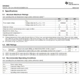
Specs are as follows; IMG_20200213_8159.jpg
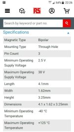
After several hours more work I got the halls in, but the motor doesn't go :(
When I tested the halls on my dmm, I was only getting 2v Max on (3.5v supply) but they turned on and off as expected.
The motor just locks straight up, doesn't try to turn. It's not the phase/hall combo....and I tried other combos just to be sure, with same result.
I'm suspecting I screwed up with the hall selection, which is confusing bc they seem a good match. However I am suspicious on the 2v issue. The original ones were 3.5v Max and seemed to turn on /off whereas the new ones output seems proportional the the magnetic field strength.
Can anybody shed light on this?
Also wondering if they sent me the wrong parts...nil Texas instruments markings on them?
Cheers K
 
From your data sheet the hall you chose it seems the normal return voltage is 2v with a maximum of 2.5v. I don't know what your controller needs as a return voltage, but a low return voltage might be the problem. However, the Honeywell SS41 Halls that many (most?) use needs a 4.5v input voltage minimum, with a maximum output of 20v. Mine latch on and off at about 4.8v to 4.9v.

This makes me wonder about your controller input voltage.

Q. Do you know for sure what the old Halls were?

Data sheet info:
dvr5053.jpg

http://www.ti.com/lit/ds/symlink/drv5053.pdf
https://sensing.honeywell.com/honey...ss41-l-t2-t3-s-sp-datasheet-32312814-b-en.pdf

:D :bolt:
 
Damn! I missed that spec, thanks for picking that up e-beach. I haven't measured the controller voltage but I assumed it was ~5v. I would be pretty confident that that is the issue....sigh, now to get that epoxy off :(
Cheers
 
if it helps, the way the controller reads the hall sensors is by detecting the grounding of a sensor.

the hall sensors in a motor are open-collector output, which means that the controller has resistors inside it that connect each hall signal up to 5v (because the sensors themselves don't have anything in them that goes to 5v internally).

then when the magnets in the motor pass the halls, they turn the hall on, which cuases teh hall to ground the 5v.


so...if the halls you have aren't open-collector output, they won't work the way the controller expects, and results may unexpected operation.


there are a number of "clones" of the ss411a honeywell sensor, many of them with "41" or "411" in the part number. pretty much any of them should work in a typical ebike motor.

but if you can, i'd just get the "real thing" at digikey or mouser or farnell or some similar place. they should cost less than $2usd each; it's going to cost more for shipping than the parts (so you could buy more than you need, and then resell the extras here on es in the for sale section, there's always somebody that needs some, local to some other es member, so they can be cheaply mailed in a regular letter envelope).

https://www.google.com/search?q=honeywell+ss411a&newwindow=1&source=lnms&tbm=shop
 
kdog said:
When I tested the halls on my dmm, I was only getting 2v Max on (3.5v supply) but they turned on and off as expected.
3.5v isn't normal supply voltage. they should be getting 4.5-5v at the vcc (+v power supply pin).
you should check the controller's 5v output line, it could have been damaged at the same time as the halls. this can probably be fixed by replacing the 78l05 which looks kinda like the hall sensors do, inside the controller.

so could the controller mcu itself, because the hall signal line inputs are not usually protected from external voltages--that's not fixable, and would need a new controller.

also, anything else that was on the 5v line (throttle, etc) can also be damaged during motor cable damage incidents, if halls were damaged.


the halls shoudl also be getting 4.5-5v minimum on the signal pin, except when a magnet passes them, when they should drop to 0-0.8v or so. if they don't, the controller won't recognize the signals correctly.


I'm suspecting I screwed up with the hall selection, which is confusing bc they seem a good match. However I am suspicious on the 2v issue. The original ones were 3.5v Max and seemed to turn on /off whereas the new ones output seems proportional the the magnetic field strength.

yeah, it looks like that's the way this particular part works. it's an analog (sometimes called linear) output.

the type you need is a switching (not analog) type; usually they're also called bipolar, like this one, but the output is open-collector, and doesn't output any voltage by itself, it just grounds a provided pulled-up voltage.


linear types are used in throttles. for the ones in throttles, when there is no magnet near them, typically give about 2.5v output. when there is a magnet near them, then the stronger the field is in one pole (north or south) the higher the voltage goes above that, and the stronger the field is to the other pole, the lower the voltage goes below that.

but there are other types, and that's what you appear to have in the new ones.
 
Thanks AW for the extra info. The terminology gets confusing. The supply I used to test them was a single cell 18650, hence not the 5v.
I've ordered some ss41s now... Just have to wait for them to arrive.
 
just make sure that you test motor halls with them hooked up to the controller.

if you don't then there won't be any pullup on the output, so they will appear to be "dead" as they wont' seem to change output level from "nothing". (though "nothing" is actually "on", detecting a magnet).

or you'd have to use a resistor (like a 5k-10kohm) between the hall signal line output pin and the voltage source you're using to test them with.
 
Back
Top