Hi Folks,
I've made it past testing the LVC indicators for both of my 24 channel boards... and I've started testing charging. A 19.5v laptop power supply is all I have on hand right now so I've been testing with A123 and some Headway 18650 cells I have laying around. Everything looks good so far as far as charging - the channel LEDs come on at the 3.69-ish voltage that they are supposed to and the main LED starts morphing from red to an orange-ish-green.

I have two questions at this point. The first relates to charge cutoff latching and the second relates to the main LED being on a faint red when only cells are connected.
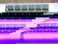
With regard to the cutoff latching I have 2 fully populated version 2.2 24-channel boards where I am testing charging on only the first 5 channels. I can short the opto outputs as shown earlier in this thread and can watch the main LED go green and feel the resistors start to cool down a bit. The problem is that when I remove the short on the opto outputs the BMS flips back to charging mode immediately with the glowing channel LEDs and an orange master LED. I am seeing the above identical behavior on both of my boards. Is it possible to get the SCR latch to lock when testing only 5 of 24 channels? As I understand it a "correctly" functioning should latch to a green main LED and stay that way until the connection charger, or really the small charger - lead, is disconnected and re-connected. In effect this "resets" the charger logic. If I have to have all 24 channels working for end-of-charge-cycle latching to work correctly then I'm happy - I just want to be sure.
With regard to the main LED being on slightly: When only the batteries are connected (on channels 1 through 4) and no connections made to the charger or the "small charger -" lead (that turns on the charging FET logic) I am seeing a faint red glow in the main LED. Again, this happens on both of my boards so whatever was done I've managed to reproduce with startling precision! This was mentioned in Patriot's build thread and now that I'm the second person to see this I thought it might warrant a comment in the main thread.
Like Patriot, I took rubbing alcohol and a toothbrush and rigorously scrubbed the solder side of the first channel segment of the BMS board. I also took a small flat-head screw driver and carefully etched the resin away from the traces that lead to Q2 and U1. After a couple of passes I feel like I have a significant amount of the cleaned away from the solder side of the board. When I connect the first 4 cells (with a 0.62", 5-pin polarized molex connector) the main LED starts to glow a faint red. I can disconnect the cells from my BMS board A and connect them to my BMS board B and get the same effect. I've scrubbed and scraped both boards.
I took some volt measurements on both boards and they were identical to +/- 0.01 volts on each board:
14.04v from "Pack -" to "Pack + after cell 4".
13.76v from "Charger -" to "Pack + after cell 4".
4.31v from "Charger -" to "Small Charger - Lead"
9.30v from "Small Charger - Lead" to "Pack + after cell 4".
Does anyone have any suggestions on what I might try to isolate the cause of LED staying mildly red with no charger connections? If I comprehended Fechter's notes in Patriot's thread it has to do with the sensitivity of Q2 and some voltage being picked up from somewhere causing the transistor to switch and turn on the charge-control logic (and thus the red LED signal). Is there some procedure I can trace with a multimeter to maybe isolate where the voltage is coming from?
Thanks,
--Adam