The SB Cruiser : Amberwolf's 2WD Heavy Cargo Trike & Dog Carrier

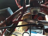
today: replaced the old turn signals in front. the leftside signal had been intermittent for a while, then stopped working altogether. the led strip on the same fork leg still works fine, so it's not a wiring issue up to that point. since i have wanted to change to a "fancier" style of signals (that match the rear ones in lenses) i just went ahead and did that, instead of troubleshooting these. but while wiring up the new ones, i found it *was* a wiring fault, broken conductor inside the insulation, between the point the led strip joins the cable and the left turn signal itself. :/

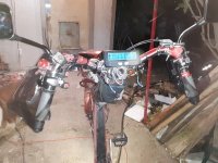
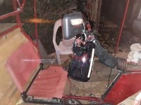
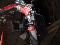
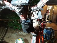
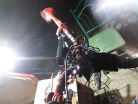
the old signals bolted tot he sides of a "y" frame i'd built into the headlight support. the new ones have their own "wing style" supports (actually they're for the rear, but i like the look on the front instead), but the bolt holes / mounting plate are at a sloping-back angle so i couldn't just put them on, i had to put a matching mounting point on the headlight support. this meant altering the headlight support itself, but at the time i got these signals i hadn't yet figured out how to do it easily.

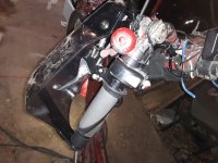
today, i figured that out just looking at it...poof the idea was there. :) just grind the twin tubes at the top at a matching angle to the supports, then weld two "nut plates" i had saved from something (don't recall what) to those. i put bolts in the holes during welding to keep the threads clear, then took them out and reground the faces flat so the signal mounts would sit correctly. bolted on, and voila!
20200402_110039.jpg
20200402_110045.jpg
20200402_110051.jpg
20200402_110058.jpg

of course, i didn't do it all alone, i had help from my supervisors:
20200402_110102.jpg
20200402_110114.jpg


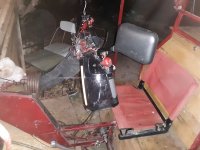
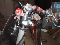
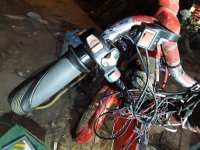
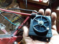
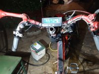
the next thing was to fix the side-looking mirror on the front. since the fork changeover, it hasn't been aimable far enough upward, so i have to lean forward and down to use it to see past corners, parked cars, etc. to fix this, i had to open it up and remove some material from the ball-joint holder of each mirror, so they could pivot farther upward. easy to do, but had to cut the plastic apart to get the unit itself open first, and didn't want to destroy it. so now i can use it like it was meant to be (sort of...it's actually supposed to go on a car's trunk to do this job).

20200402_110319.jpg
20200402_110323.jpg
20200402_110327.jpg

it's still just ziptied to the headlight support frame, rather than bolting it on, but it is very lightweight, so not a problem.


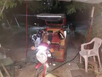
--added an led bar over the kia headlight
now, since it was meant for a car trunk, it has a place for a red light bar in it, for a brake light, etc. but i have it in front...so why not a white light bar? i took an old aquarium 12v led strip, cut it in two sections (with a couple leds leftover that wont' fit), and used silicone to "glue" tehm down inside the mirror unit behind the clear cover area. they're bright enough to see in daylight. presently is switched on with all the other lighting (except headlight and canopy/cargotopdeck lights).
20200402_135319.jpg
20200402_135324.jpg
20200402_135335.jpg
20200402_135358.jpg


20200402_185843.jpg
20200402_185856.jpg
20200402_185920.jpg


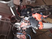
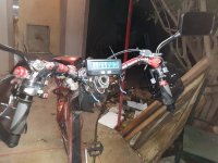
--moved the grin led headlight and disconnected it for now
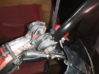
while i was tying this down, and putting the reflector back on for the left side front (came off with turn signals), i moved the grin tech led headlight from the right side over to the left, above the reflector. wasn't room for it before. the epoxy or whatever casing of this light is aging poorly. chunks have fallen off, and the mount hasn't been part of it for a while so it's been ziptied around it to the bracket on the trike. even the button extender is gone, for the power/mode switch. can still poke it with something to change it, but don't need to. it just stays in the steady-on mode. the outer two rows of leds usually don't light up anymore, occasionally they will flicker at random superfast rates. the middle two still work. i'm only leaving it on the trike at all in case other front lighting fails, as a marker light, since it has such a wide voltage input range i can use it with whatever battery is still working on the trike. ;) but i left it unplugged, as i have plenty of other lighting up there now.


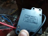
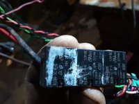
--removed the failed left throttle after impossible repair attempt
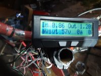
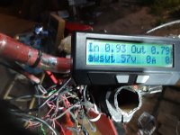
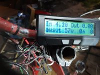
now, this was a disaster. :/ this throttle was causing intermittent problems that took me months to narrow down, and that only happened because it finally died. the problems were that the pas would just stop responding, but throttle didnt' appear to work either. sometimes. sometimes it would. the ca main screen showed the pas sensor input working normally, with the icon in the lower left corner, so it had to be something else. the throttles worked perfectly, so it couldn't be those, right? :roll: i thought it might be a ca issue, firmware bug or hardware issue in the ca, etc.

but then sometimes the left throttle would stick "on" just enough to cause the ca to see a throttle input...which means that it disables the pas control. the right throttle would still override it. but sometimes the left throttle would apparently be stuck at a much higher than normal voltage, well over four volts, and that would disable all throttle input (and the pas). if i flicked the throttel, it would work again, sometimes. then the throttle just plain died, no output at all.

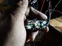
since its' the last of my "good" thumb throttles, i gave it a shot to fix it. no votlage output regardless of connection conditions, input voltage, positon, etc., opened it up and found the hall was ripped off inside, and one magnet floating around in there. :/ well, the hall was an easy fix. i have a bunch of full-grip twist throttles, so i pulled the senosr and cable off one of those (they're not glued in so it's easy), then moved it to this throttle. wired it up, and then began experimenting with the magnet reinstallation positions. it's not quite square, so there's only four total postions the bar magnet can go in. should be easy, right?

:roll:

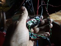
i apparently forgot to take pics, but i went thru every possible variation of magnet postion, and could never get below about 1.4v on the low end, up to 4v with some positions. i tried comparing with another similar thumb throttle (with broken thumb tab), but every position seemed to match, everything wa salways attracted, never repelled. after an hour o r two i gave up on it, and decided for now i'll live with just the righthand throttle. i d'nt need itmuch, almost always just ot start from a stop when i can't push on the cranks hard enough without pain, to get started enough for power to kick in.


EDIT (060620): I found the reason for the "impossible" magnet problem:
https://endless-sphere.com/forums/viewtopic.php?f=2&t=37190#p541271
fechter said:
The two magnet hall throttles use an interesting magnetic configuration. The low side magnet (closest to sensor at zero throttle) is magnetized radially, that is the poles are faced 90 deg to the direction of movement. The magnet on the high side is magnetized with the poles parallel to the direction of movement.
which explains why no matter what I did, the throttle would never work. Now that I know this, I might be able to fix the problem, if I ever need a regular throttle type throttle (have been working on changing over to COT (cable operated throttle) units, to prevent ever needing to deal with fixing the problems that happen with these cheap handlebar-mounted plastic ebike throttles).
(end edit)


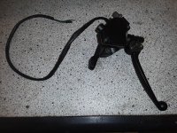
--removed the temporary rigged brake wire/tape system from the right brake lever (front disc). it worked fine but don't need it now, because of the next post's work.

--repaired the rear top-bar red led strip; the left half had gone dead a while back, found a part of the strip had internally corroded under the silicone. cut it out and replaced with new section, soldered it in and siliconed the gaps.

--removed the dead white led strip under the left handlebar
dunnow when it failed, bu ti's toast now.

the next post goes into detail on the prop-regen/brake lever.
 
--replaced the left brake-light-only lever with system to handle ebrake, brake light, and proportional regen

because i'm using hte cycle analyst v3, this setup is simpler than if i were directly controlling the braking of the grinfineons. the gf's use the throttle input for prop braking control--if it goes below 0.8v, it assumes y'ure braking, and the closer to zero, the more braking it gives. so directly doing that requires some electronics; didnt' have to do that for the ca v3.

the ca v3 has a mode where it takes an ebrake switch input, recognizes you're pulling the brake lever, and then uses the throttle amount to control braking. teh higher the throttle input, the more braking. because it is very confusing to use the throttle to modulate a brake signal *while still using the brake lever just a tiny bit to keep you in braking mode*, and would lengthen reaction time significantly, potentially causing serious results when riding in traffic, etc., i instead chose to use the brake lever on the left, which doesnt' have a mechanical brake on it, just using the ebrake swithc to turn on brake ligths, to instead do three things, using three relays (one 3pdt would work,but i didnt' have that, so used three spdt's off a board saved out of a dead ups.

the brake lever is wired from 12v lighting power positive to the top of teh three relay coils (in parallel with each other). the bottom of the coils goes to lighting ground. so pulling the lever turns on the relays.

the first relay just goes between the brake light power and the brake ligths, on it's no contacts.

the second relay just goes between the brake switch input wires on the ca (and to the nongrinfineon generic controller on the right side, so it will do it's regen, which is several times stronger than the grinfineons, but is not proportional, just on/off).

the third relay goes between the throttle output signal wire of a cable-operated-throttle (cot) and the ca's throttle input wire (the ca's input is paralleled with the regular throttle on the rigth side as well). so this throttle is not connected except when braking. (the plan is at some point to put the signal wire from the regular throttle on the nc contact of this relay, so it literlaly switches between the two throttle sources, but at the moment it leaves the regular throttle connected; that's problematic under some situations, like emergency braking while the throttle was maxed--that will instantly give full braking, which may not be what was wanted).


the cot unit is moved via cable from the brake lever, in place of a brake. by a wierd coincidence, the cheap wuxing lever i chose happens to have, with the handlebars it's on, exactly enough travel to fully pull the cot reel all teh way, though tensioning it enough required putting the adjsutment nuts literally all the way out, so later i'll find "longer" nuts that fit (or weld some together) and put them on the adjusters, so that it isn't sitting catawumpus liek it si now. it works, but i'd prefer alignment better.


the ca settings just need prop regen enabled, and set to 0.8v start, for the ca to take the brake signal and begin activating braking. it will then send the braking signal to the throttle output (for grinfineons and phaserunners, for example), starting at 0.8v, whic just barely turns on braking at all, then continuing down to 0.0v for full braking at full lever pull.


there are other details but i'm dozing off a lot, so will just post this now, and come back later to add more if i remember it.


so, if you want to use your brake lever to control proportional regen braking, and use a cycle analyst.
 

Attachments

  • 20200402_185703.jpg
    20200402_185703.jpg
    42 KB · Views: 3,111
  • 20200402_185714.jpg
    20200402_185714.jpg
    44.3 KB · Views: 3,111
  • 20200402_185707.jpg
    20200402_185707.jpg
    48 KB · Views: 3,111
  • 20200402_185816.jpg
    20200402_185816.jpg
    61.9 KB · Views: 3,111
  • 20200402_193046.jpg
    20200402_193046.jpg
    48.4 KB · Views: 3,111
  • 20200402_193042.jpg
    20200402_193042.jpg
    32.5 KB · Views: 3,111
  • 20200402_193106.jpg
    20200402_193106.jpg
    33.6 KB · Views: 3,111
  • 20200402_193253.jpg
    20200402_193253.jpg
    35.5 KB · Views: 3,111
  • 20200402_193059.jpg
    20200402_193059.jpg
    38 KB · Views: 3,111
  • 20200402_193115.jpg
    20200402_193115.jpg
    39.7 KB · Views: 3,110
  • 20200402_193304(0).jpg
    20200402_193304(0).jpg
    39.2 KB · Views: 3,110
  • 20200402_195650.jpg
    20200402_195650.jpg
    52.7 KB · Views: 3,110
  • 20200402_195657.jpg
    20200402_195657.jpg
    58.7 KB · Views: 3,110
  • 20200402_195705.jpg
    20200402_195705.jpg
    40.1 KB · Views: 3,111
couple of issues:

--i forgot to also add a brake light switch to the righthand lever, so i can activate just hte brake light without actually braking (to just signal that i'm coming to a stop, or slowing by coasting down, a frequent circumstance). the left lever, using the relay to switch on brake light and ebrake at the same time, will always drag the trike down in speed rapidly, because the righthand controller that's hooked to that ebrake line doesn't have proportional regen, just pretty strong on/off regen.

so i hacked a switch into the righthand lever, which is the mechanical front disc brake lever, by ziptying a spare speedo sensor wand (n.o. reed switch) to the brake lever mounting, parallel to the lever, and gluing a short stack of old badge magnets to the end of the old badge magnet bar, and ziptied that to the lever itself nearby, perpendicular to the bar. sliding the bar around in the zipties on the lever to adjust responsiveness, so it engages the brake light before the pads begin to touch (much), took a little while. then i glued the bar in place, leaving the zipties as well. it's just wired parallel to the relay's brake light contacts, so either one will turn on the brake light as needed.


--the next is a harder to fix issue, which i'm not sure is fixed yet. i'm not sure of the source of the problem yet, but it seems to be noise in the ground of the throttle, but *only* when a throttle (apparently any throttle) is plugged into the connector for the lefthand throttle plug (presently occupied by the cot that creates the prop regen signal). it doesnt' matter if the *signal* line is hooked up to the throttle's signal line, becuase this problem happens when the cot relay is off, cutting off the cot signal wire (but not it's 5v and ground).

but the symptom is that in the ca's diagnostic screen, if i'm using just the pas (cadence only atm), the throttle input voltage jitters significantly, and the more power the trike is using at a faster speed, the bigger the jitter, until it begins going above the minimum throttle input that the ca will respond to. at that point it begins interfering with the pas control (because the ca prioritizes throttle over pas, so anytime there is even a tiny amoutn of throttle inptu above the min value set in the ca, it uses that isntead of the pas input, even if the pas input is much much higher). so since it's jittering, the trike shudders as power cuts off and comes back on, as the ca switches between the spiked-up throttle voltage (that is still tiny, probably only a volt or so; flickers too fast to tell) and then back to the pas signal. by the time the trike is up to about 17-18mph, it's impossible to get any faster becuase it cuts out so much.


so...hoping it's electrical noise, i've put a 0.1uf ceramic cap across the throttle input signal and ground.

i *think* i already eliminated bad grounds...but can't be totally certain. i went thru all the wiring with the throttles and the ca signals, and everything tests ok for continuity, and i see no dc voltages on any grounds just sitting there (but can't yet test it while riding).

i was too tired by the time i got done with all that tonight to go test ride it, so i'll see how it works tomorrow on my work commute.


that said, the cot lever / relay system for prop regen works well. if the grinfineon had enough regen current it would probably be perfect (and if i had them on both motors). it's just strong enough that if i am at say, 20mph and i pull the lever, it engages the righthand motor's on/off regen, which drags the trike to the right, then as i pull the lever to the bars, i can feel the leftside motor dragging harder and harder with more and more regen, though it's never as strong as the righthand one (which itself isn't strong enough).


so, once i have controllers that can create sufficient regen, and support proportional regen, then this lever system should work perfectly to do this.
 
both the capacitor on the throttle input of the ca, and the rigged brake light swithc on the right lever, worked perfectly.

now there is at most (and usually not even) a hundredth of a volt of jitter on the throttle input, per the ca's diagnostic screen while riding.


so, two issues down, nine billion to go. ;)
 
With my annual housefire-trauma vacation starting the middle of this coming week, I've been collecting the bits to massively upgrade the motor controllers to something with Lebowski brains.

The hard part was deciding what powerstage to use, becuase I did NOT want to build something "from scratch"...I'll never finish it if I start. Just too many things to do, and not enough energy, time, and too often not enough ability (either eyesight or hand problems or both).

So after some discussion in one of the Lebowski main threads, I went with the Honda IMA Inverter as the cheapest (REALLY cheap for what you get!) compatible powerstage with my needs, vs the size, cost, complexity. They're not ideal, being IGBT instead of FET, as I'm only using 14s (less than 60v full), and IGBTs don't start being a better choice than FET until over 100v. But they should work fine (if less efficiently) at my lower voltage, and I might eventually go up that high (28s) for a number of reasons, if the option is there. Using these makes that simple if I do.

Unfortunatley they're not small; I could probably fit three or four typical 12FET controllers inside the volume one of these takes up, and their heatsinks are large and heavy, making them nearly 11lbs each. If it gets me what I want for features, and is dead-on reliable, I'll live with it.

file.php


file.php


file.php


This thread:
Lebowski SMD brain running a zombified Honda IMA Inverter: *a HOW-TO guide*
will be my adventure into connecting up a Kiwifiat-built Bobc-designed SMD Lebowski brain to the Honda IMA Inverter. All of the details of that will be in that thread, up until they work and they get built into the trike. Hopefully it will also help others use these powerstages.

There will be a pair of them, one for each of the rear hubmotors, and I will probably use the throttle link these brains have to run them both off of a single throttle.

I'll still be using the Cycle Analyst v3 to generate that throttle based off of my PAS and the (redundancy) thumb throttle.

The analog-regen ebrake setup I made using the COT unit with an old ebrake handle to pull it's cable and engage a relay to switch over will be modified to pass the COT output directly to the Lebowski brains' analog ebrake (second throttle) input, to control the negative torque used for braking. This should be much more useful than the present setup that goes thru the CA3 to translate into a throttle-voltage-range for the Grinfineon, and it should also give powerful braking that the Grinfineon simply cannot do. THAT is one of the most important things I need to have, is braking powerful enough to practically slam the trike to a stop from 20mph if I need it to (without skidding the wheels, preferably, but if it can do that, then it even makes it to the "legal" version of braking).

Of course, the motor axles will have to survive that, too, but they won't be getting a sudden on/off regen burst like with the generic controller that does the best I've had for that type of brake (pretty good, but nowhere near good enough...still about perhaps twice the braking the Grinfineon can do at maximum).

Theoretically the IMA inverter can do 15kw continuous, with fan aircooling of that heatsink. Peak, I don't know. But I dont' even need half that as *peak*, maybe only a quarter, and practically nothing continuous. It'll be doing so little work compared to it's design that it might take naps during a commute. :lol:

I'd like to get about 8kw total, minimum, 16kw total if I can make it happen, for startups from a complete stop with a full 350lb+ load in the back of the trike, plus a trailer full of dog or food or...whatever. That way I can get started and up to 20mph as quickly as possible, for those rare but persistent occasions when there is some impatient driver waiting behind me at a red-light-just-turned-green that just *CAN'T WAIT* literally two seconds or less for me to accelerate thru the intersection and out of their way. Or to be able to accelerate out of the way of someone changing lanes into the spot I'm presently occupying (and when braking is only going to get me crushed by traffic behind me that can't possibly stop in time even if they were to try).

It would also be nice to have the power just for hauling things up slopes, though they would have to be short ones so as not to destroy the motors themselves from overheating. ;) They're only poor little MXUS 450x hubs, theoretically 3kw in a 20" wheel (and mine are technically 20" but realistically 22" outside diameter for the tires on there)>

I won't need the power often...but when I do need it, I *really* need it.

Just don't tell anyone it might be more fun, too. ;)
 
I finally got an LCR meter, the DE5000, and used it to test the phase-to-phase inductance and resistance of the QS205 50H v3 5T (so 24x5 per QSmotor's charts) that I got from Shortcircuit911, as a comparison to see how far different this meter might read vs manufacturer data, simply because there *is* manufacturer test data for this motor type.

HOwever, it is VERY different.

The details:
https://endless-sphere.com/forums/viewtopic.php?f=2&t=105637&p=1549398#p1549398

The basics:
It should be 300-330uH, but i get about 98uH average, from any phase to any other phase.

It should be 64.90milliohms, but I get about 31milliohms, from any phase to any other phase.

So not sure if the meter is messed up, or I am doing ti wrong, or QSmotor's data is wrong. All testing done with the stator out of the rotor, so no magnets to mess any readings up.


I'm going to go test all the other hubmotors I have access to, to see what results I get. Most of them are still in their rotors, so the magnets will affect the readings, by how much I don't know.
 
Not been feeling well the last couple days, but today was better, so I got a few things done on the HI-Lebowski controller project:

https://endless-sphere.com/forums/viewtopic.php?f=30&t=105711&p=1550413#p1550413

The main thing was to move the existing controllers to make room for the new ones (leaving the old ones there for quick changeover if necessary to get home).
file.php


cuz the new ones are a lot bigger and fill that whole space between the wheels
file.php


The other thing was to start work on a subframe to bolt the new ones to that will itself then bolt to the frame of the trike (where the old ones were light enough to just screw to the wood).


I had planned to be building the new wheelwell frames for larger wheels (starting with the largest version of the Shinko SR714 I can find, a 90/90, that should be around 3.5" vs the 2.25" I'm using now, and should make the wheels almost 26" diameter vs teh 22" or so they are now), for better ride quality especially when heavily loaded.

But we have had a heatwave about ten to fifteen degrees above normal for this time of year, so it's been 102-105F highs, and 70s for lows just before dawn, and I just wasn't physically ready for that yet (it shouldn't be like taht until late May, a month from now!). So I have been doing stuff inside instead, which is not nearly as productive as the work I really should be doing on the trike. Today was one of the cooler days, and tomorrow is expected to be almost the same, bit warmer, then it goes up again for the last couple days of my time off, likely even hotter than it has been. Of course, as soon as my time off is over, it goes back down to the 90's, though the high end of that rather than the low end (or even high 80s) like it should be. :(

Oh...and the flies.... the FLIES...they want to eat me! There must be a bajillion of them.... the only way I could keep them off me was by watering around the yard (except where I would be) before starting, and then sprinkling / misting down some of the farther areas periodically as stuff dried. I tried OFF! in two versions but the flies just think it's seasoning. :/

At night, I have to leave all the lights on except where I'm working, then use light there only when I have to, or teh flies come over to buzz around. Maybe if I leave the lights on all night they'll be too tired to buzz me tomorrow. No? Well, it was a thought.... :(
 
Still working on documenting and completing the HIL controller project above, is slow going, because if I don't do the complete documentation while I do the work, I will honestly probably never document it well enough for others to follow along. :oops:


In the meantime, a distraction:

On the way home from work on Friday, I just had an impulse to check Goodwill, which I haven't stopped at since this whole covid thing started back in March, I think it was. There's usually nothing I'm willing to spend money on, but this time there were four small solar panels, for not much more than $30, in good condition. Three are the cheap ones like you might get in an old HarborFreight solar kit; the fourth is a nicer Kyocera panel, about twice as powerful for the size and weight.

This is the thread about them and some basic testing, to see if it's worth installing them on the trike (it's not):
https://endless-sphere.com/forums/viewtopic.php?f=41&t=106119
If they were all the Kyocera panels, I probably would put three of them on there anyway. For grins I looked around, and while the Kyocera is long-discontinued, there are some direct replacements out there that have similar performance...for up to nearly $300 each. No thanks. Some cheaper similar ones that *might* be similar performance are $50-$100 each. Yeah, no, not worth that. $10 each, I'd maybe do that. Or a single $40 panel the size of the top of the trike, that would do 150w, at 60v output open-circuit. (I don't think those exist.)

But it *would* add a bit of "cool factor" to the trike (if it didn't have enough yet), to be able to say it's at least partly solar powered. ;)

file.php
 
Regarding the new wheel-moutning method, rear disc brakes, etc here:
https://www.endless-sphere.com/forums/viewtopic.php?f=2&t=67833&start=950#p1505162

I've been working out how I could change out to a bigger diameter wheel (or tire on the same wheel), for a better ride in back with loads and still no suspension (which complicates things too much).


First, contemplating just using the 90/80 version of the Shinko SR714 tire,
https://www.amazon.com/dp/B001CD57X4
SR714-90-80.jpg
vs the 2.5" version I'm using now:
https://www.amazon.com/dp/B00274F0G6
SR714-2.5-16.jpg

because the 90/80 *should* be considerably larger outer diameter, on the same size rim (about 45mm?). If I calculated correctly, 2.5" is about 63mm. Not sure if it's intended to be 2.5" high *and* wide, as it doesnt' have a spec to say one way or the other, and the Shinko site itself doesn't have complete details on most of their tires (some of them don't even show up on the site at all, and at the moment the site is broken and won't let me access much of anything).

If it is supposed to be the same high and wide (whcih it approximately is on my rim), then let's say its' 63mm x 2 taller than the rim itself, which is 16" (or 406mm), for a total of 532mm, or 21". I'm pretty sure it's actually taller than that but I have to go measure it. 1670

So if the 90/80 is actually 90mm taller than the rim, then total wheel diameter would be 90 * 2 + 406 = 586mm, or 23", which is a significant change.

I think it would be 1840mm circumference, vs about 2500mm for my front 26" tire, or 1670mm for the 2.5" x 16 tire.

That *should* make a noticeable difference in rolling over road problems, plus the fact the tire has a lot more air volume and some greater distance from tread to rim.


But I haven't been able to locate anything that actually *verifies* that this 90/80 tire would be any larger (much less that much larger) than the 2.5". There are some pages (including the amazon linked above) that actually say it is exactly the same size, just wider, and marked in metric vs imperial. I doubt that this is correct, but I cannot find anything certain that tells me. Don't really feel like spending basically $84 on a pair if they aren't going to give me that much improvement; I'd rather try to figure out another way, or another tire that would fit on the same rims. (would rather not have to get bigger heavier MC rims and tires just to get bigger rear wheels).

If I could find a moped/etc tire with the rectangular profile of the Innova IA-2098-1 20x3
https://www.ebay.com/itm/153844435594?hash=item23d1d7ca8a:g:JyQAAOSwfiReVDbW
I'd prefer that, but everything I run across is rounded profile.
5.jpg


Assuming that this tire *would* do the job, it's going to both raise the trike's rear end another inch, *and* stick up enough to require removing (or enlarging) the whole wheel well. It's also going to be wide enough to require expanding the wheel well outward significantly (which needs doing anyway in order to install the disc brakes back there).

So with that in mind, I'd rather rebuild the rear support frame to triangulate it and put the dropouts *above* the deck, which improves the strength of the whole thing, and makes it much easier to get the wheel off for servicing (though doing it the way it's linked in the first part of this thread would also do the latter). Depending on how this is done, it would also widen the rear track, making the trike even more stable in turns.

An easy way to do it as a test is just to add the whole frame to the outboard side of each side of the trike, first welding it up and then bolting it on. This would look something like this, first with a 26" wheel placed as far rearward as possible, and then with a 24" just a few inches back from the current position.

20200514_134017.jpg
20200514_134542.jpg


Unfortunately this has at least two problems: It adds at least a foot to the trike's width, and it makes the pedal drivetrain unable to connect to the wheel anymore, without extending the shaft and support for the transfer shaft, by at least six inches, to keep the output sprocket aligned with the wheel's freewheel.
20200514_134045.jpg
20200514_134106.jpg


The latter isnt' a huge deal, but the former means I could almost certainly no longer get it around at least one of the corners inside the store I work at, to get it to the breakroom, by a couple of inches or so (guesstimate).


The width is reasonably easy to deal with. I can use just the outermost outboard triangulation frame section, added to the trike's existing framework, and remove the present outboard wheel-well and outboard lowest frame members, and wood panels in that area, and a couple of the panels of deck at the outboard edges right behind the wheel wells. Then put the inboard triangulation frame members in place of the old inboard wheel-well frame members, or just outboard of that position, and it would then only add about six inches to the trike width. That would be livable, should still fit well enough around the tightest corners at work.


This version wouldn't widen the track by as much for stability, but it would still be at least 3" (more like 4 becuase of the tire position within the frame) wider, and the tire and frame weight added would be at these outboard edges, making better "anchors" in the turn.

I'm not sure what effect moving the contact patch rearward will have, but that is inevitable with larger diameter tires, as there is not enough space for good clearance between the front of the tire and the back of the seatbox/frame. It will only *have* to move back about an inch, but I'd actually prefer to move it back as far as possible, so that more of the cargo deck is between the wheels, making for more traction on the front wheel when loaded (especially when pulling the trailer).

20200514_134708.jpg
20200514_134718(0).jpg
 
Been sick a while, so nothing new with the above stuff yet.

Even though I've been stuck home much of the last few weeks, I've been too worn out to even sit at the worktable and wire things. For the last week, too tired to even post on ES, mostly dozing/waking and sometimes letting youtube science videos play when I could concentrate. Sometimes poking around on Amazon and Ebay for wierd things I might be able to use. (didn't find much). The days I have made it to work I coudln't do much, and went home early a fair bit.

I'm still very tired, and fairly weak--just hobbling around the yard with the dogs for a few minutes can put me back in bed for hours. But I am having longer periods of activity-capable time, more often, so I might accomplish something "soon" (next week or two). Just not completely sure of myself in delicate work like the wiring and such still to be done. (I find myself dozing off randomly sometimes, too, which is a problem when soldering and the like).

As there are other assorted things I may accomplish (or start) with the trike and some other household projects, I'll post a version of this in those threads too.


Rix did work out for me that the tire stuff above won't make *much* difference, maybe an inch, inch and a half at most for additional diameter. May not be worth doing for the huge amount of work needed to get them on there (complete frame rebuild, etc, for the rear...though I still have to do that anyway to install disc brakes, so....maybe....someday). So for now, I'll hold off on the expensive bigger tires, and just replace the one worn-out rightside rear tire with another of teh same narrower versions. I don't know how long it will be before I can actually do the replacement, though...I don't have the energy. If it shows up while I'm still on time-off from work, I can do a part of the work each day and get it done before going back to work. But if I run out of time-off first, it's probably going to have to wait until it fails. :(


Once any of these things actually arrives, I'll see about getting pics posted up.

In the meantime, one of the wierd things I found on Amazon was this:
https://www.amazon.com/gp/product/B07GF9V6X7
(though the price has gone way up since I ordered :( )
which has a thumb throttle that pulls a cable, so should be usable with one of the cable-operated throttles to move that off the handlebars. And it's made of metal, so less likely to break the thumb tab off like so many before it. It also has a dual-cable-pull brake lever. It probably doesn't have the right pull amount to work with the Avid BB7 disc brake on the front wheel, but I'll try it anyway--the main thing, though, is to use it with the COT unit I have already setup for proportional regen braking. Having the second, separately-adjustable, cable pull is just a bonus. ;) It also has a brakelight switch built in, so I don't have to come up with something for that. If this does work with the BB7 cable, then it'll replace the kluge setup of magnet and reed swtich and whatnot on the righthand lever, as well as the lever itself, and let me control the ebraking from it at the same time as the regular braking--and be able to even setup the regular braking to not start until after the regen braking has already progressed to significant levels.

If it works out, I'll get a second one to put on the left side, which could be used to control both the disc brakes in the rear (once I do taht frame rebuild and whatnot), as well as a separate cable throttle for independent throttle control of the rear wheels once electroncis are designed and built to deal with switching/mixing the throttles vs the single-source PAS from the CA, etc.


I found some "brush guards" to replace the ugly coroplast ones I've been using for years during the colder weather to keep the wind off my hands. Since those aren't well-designed and tend to get in my way and be annoyng, I usually only leave them on when it's cold out, but during rainy seasons and whatnot sometimes I wish I had them on there.
https://www.amazon.com/gp/product/B017IMZMN2
So these will go on and hopefully be good enough to stay on year-round. They also have "reflective" stripes on them, whcih if there is room inside the guards for may get replaced with LED strip turn signals. Or just add the LED strips below or above them.


Getting tired of the problems with the (mismatched) mirrors, so also ordered these:
https://www.amazon.com/gp/product/B002309QZ0
which are basically identical to the one on the right side now, except new and not already worn-out from goodwill, so maybe will stay where I point them. ;) And not cracked, or otherwise damaged on the mirror surface. They're supposed to be glass mirrors, too, which the ones I have now are not, so there are a bunch of problems in the surfaces making htem harder to see in. I'll probably put LED strip marker/turn signals on them like i did on the similar one I'm replacing.


Considering adding "halo" LEDs around the Kia headlight, probably by wrapping multiple layers of thin clear plastic around the front outer bezel, till they're as thick as the LED strips I'm already using are wide. Make them at least an inch or two deep, for more diffusion between the LEDs and the front edge for a more continuous light strip, and then sand the forward facing edges to diffuse the light better. Then silicone the rear edges against the LED strips, and then paint the wide face of the outer layer white, then red, to contain the light within the strips. This is something I might be able to do even when this tired, because I can "walk away" from it as needed, and not have to worry about it if it's not done and I need to ride somewhere.

If it works, I might do something similar for the rear end, to outline the trike's rear end with tail and brake lights and turn signals built into the one long vertical strip on each side, and a split horizontal along the top and bottom, then once it's working, remove all the bare strips off the back face of the trike's cargo box. This would look a lot neater, and also leave the face open for other stuff. (dunno what yet). Itw ould also make the strips, if bevelled at the rear edges, visible from the sides more than the rear-facing strips are now.

This kind of thing can be done with just plexiglass or lexan, etc., for the flat trike sides, just not for the curved and odd shape of the headlight.

Could also be done on the rest of the trike wherever I have straigth strips of LED lighting.


I looked around and found LED strips that would do something similar by themselves, but they are about $50 for a couple of yards, due to the much hgiher (triple?) density of LEDs on them, vs a few bucks for the type I have now. :/
 
I finally remembered to take some updated pics of the trike in daylight. Need to get some in the dark too to show the lighting.

20200602_144228.jpg
20200602_144237.jpg
20200602_144259.jpg
20200602_144359.jpg
20200602_144345.jpg
 
I found some "brush guards" to replace the ugly coroplast ones I've been using for years during the colder weather to keep the wind off my hands. Since those aren't well-designed and tend to get in my way and be annoyng, I usually only leave them on when it's cold out, but during rainy seasons and whatnot sometimes I wish I had them on there.
https://www.amazon.com/gp/product/B017IMZMN2
So these will go on and hopefully be good enough to stay on year-round. They also have "reflective" stripes on them, whcih if there is room inside the guards for may get replaced with LED strip turn signals. Or just add the LED strips below or above them.
These arrived, and are a bit heavier duty than I expected (kinda thought they'd be flimsy). The bar-end hardware for mounting them is flexible-ish, the guards are stiff. They'll probably break in an impact, but since this is a trike not a bike, the kind of impact that would do that is unlikely. The reflector strips don't have good adhesive, and they're already peeling up at the ends, so if I keep them I'll need to glue them back down.

20200608_182828.jpg
20200608_182835.jpg
20200608_182843.jpg


amberwolf said:
In the meantime, one of the wierd things I found on Amazon was this:
https://www.amazon.com/gp/product/B07GF9V6X7
amberwolf said:
I found another brake lever unit that is useful for this:

https://www.amazon.com/gp/product/B07GF9V6X7
Some pics of this unit at the end of the post.

It's definitely all metal, and fairly heavy--have to weight it, but perhaps a pound and a half. Not exactly precision-machined or a well-designed casting, but it doesnt' have sharp edges or obvious problems, other than the brake lever itself being rather floppy, with no bushing/etc in the pivot. Not a big deal.

It does have one more feature I couldn't be certain of, just looking at the pics online, but suspected: a "parking brake" lock pin. While pulling the lever back, push the pin down, and it will lock the lever back to that position. That's a feature I've been wishing for enough to have already worked out a way to add it to my existing brake levers, but not yet gotten around to building. (lot of work).

There is also another feature I couldn't be certain of, a throttle-limit adjustment screw. Running it out lets you push the thumb tab in further, running it in limits how far you can do so. This could be used as a top-end limiter for controllers that don't have a way to adjust max throttle input, if you needed to do so fro some reason, or to match your throttle's max output to the controller's max input, if for instance the throttle was capable of a high enough output voltage that the controller would error out (rare, but possible).


The dual-pull cable uses a floating-pivot for the cable-stop holders. There's a bolt on it that may be able to tighten down to prevent the floating if that is necessary on any particular system, to prevent tension differences in the two cables from affecting each other (or it's use as a single-cable system). Might require washer(s) on the bolt to allow it to fully clamp this down.

The barrel adjusters are a bit hard to move in the threads; this will be even harder under tension. I'll grease them and see if that's still true--if so, I'll have to see if any of my taps / dies are the right size and thread for these, and chase them to see if that helps.

The angles everything is at seem to be just about perfect for fit on the trike for my usage and handlebar angle, etc., though I won't know for sure till I get it on the bars and try it.

The only two things it doesnt' have that I would like are a mirror mount hole, and a barrel adjuster for the throttle cable.
Bottom  20200608_183052.jpg
END   20200608_183104.jpg
Front   20200608_183041.jpg
Inboard end 20200608_183123.jpg
Inside throttle pul box 20200608_183504.jpg
Lever locked   20200608_183013.jpg
Lever unpulled    20200608_183003.jpg
TOP   20200608_183111.jpg
 

Attachments

  • 20200608_182949.jpg
    20200608_182949.jpg
    69.3 KB · Views: 2,755
Took me all day, off and on between rests, but I got the throttle/lever unit, the mirrors (which arrived today), and the handguards installed.

The ATV thumb-cable-throttle / dual-pull brake lever combo was something of a PITA to install--it required filing with a round file on the outside of the "chamber" for the throttle pivot to clear the bars, because this is molded such that this vertical cylinder is in the path of the tube of the bars passing thru the clamp. :roll: It's aluminum, so it was not difficult to file, but it cannot be installed at all until this is done--at least 1/16" must be removed to do it. :(


As expected, the amount of pull (mechanical advantage) of this lever is insufficient to use on the Avid BB7 disc. So I'll have to look up how to make a pulley like the Travel Agent to fix that.
https://www.parktool.com/blog/repair-help/travel-agent-installation-and-adjustment
I might be able to make an "extension" on the lever itself for the puller piece, since that unbolts from the lever, so it sticks out farther from the pivot point and thus pulls more cable for the same lever travel. That's probably easier than a pulley to make and setup, but dunno how well it will work with the adjusters--may hit them and cause friction.

In the meantime, I simply left the lever off, and mounted the rest of the unit (throttle puller), and put hte Avid lever on just outboard of it, and used the adjuster on the ATV unit (since there's no space for the AVid's adjuster or routing the cable *around* the ATV unit body, I just passed it thru).

Cabled up the throtle lever to my spare COT unit. It doesn't have the complete full travel, maybe 3/4 of it. Easy to deal with in the Cycle Analyst--I just changed the throttle input range to match what I get, around 0.9v to about 3.4v. The CA will then simply translate that to the already-setup output range.

The throttle lever has a lot of play in the pivot, like the brake lever, so I installed a plastic shim made from the packaging of the mirrrors. I would've used a brass shim but I cannot find the ultra-thin brass sheet (that can be cut with scissors) I keep around for such things. :( The pivot shim actually increased the range from 0.9v-2.3v up to 0.9v-3.4v, must be something about the angle things are at without it that doesnt' pull as much cable.

That makes me consider dremelling out the little "nut" molded into the casing for the top-limit screw, as that would give enough movement to get even more range out of the throttle.

But even as it is, it's smooth, and takes just enough force to move that it is MUCH eaiser to control amount of throttle input, so I can control it at low speed much more easily than with the Grin Tech thumb throttle I'd been using (or any of the old WuXing ones before that). The position and direction of movement is enough differnet it's going to take a while to get used to...but it's comfortable enough so far, just sitting there playing with it, with the CA in setup mode on the Throttle In screen to watch the voltage range, and then riding very slowly around the yard in the post-sunset almost-dark.

This is good, because I'll need that kind of ease of control with the higher power HIL controllers, once I get back to those and finish them up.


I would've just put it on the left side, upside down, but the throttle section will not clear the light controls no matter what configuration anything is put in over there. A shame, because it would've let me use it for both the ebrake and the throttle on that side. I *could* have just switched all that to the right side, and put the front mechanical on the left, but I am so used to front on the right that it would take time to relearn, and my many years of muscletraining might make me do the wrong thing in an emergency. :(


I also installed the handguards; they look ok. The expansion nuts that go inside the bar-end mounts are plastic, though, and one of them disappeared while I was trying to stick the bar-end hardware in and my hand went numb, so had to find and use a regular nut. Didnt' work as well as the conical expansion nut, but it does secure ti well enough along with the "mirror mount" bar (which is presently ziptied to my version of a mirror mount since the angle is wrong to be able to use it as designed, unless I can twist the mount bar (not strong enough right now to even try).


Installing hte mirrors was the easiest part, and the hardest part of that was getting a seatpost mount off an old ripped up seat,, and loosening and tightening the nuts at various stages. I am still weak, though better than I was. Only one has a turn signal on it ATM, because the left mirror had it built in, and I don't know where I put the one I'd made for that side on the old mirror before that one. Have to make a new one probably. So only the existing right signal was resetup, screwed onto the housing of the right mirror just like it was on the previous one (the new mirrors are virtually identical in design to that one, except they are both intact, and have glass mirrors instead of plastic.)

As I don't have normal threaded mirror mounts, I use old seatpost mounts for this, minus half of one side's hardware to allow the length to clamp onto the 10mm threaded post of the mirror, much thicker than the seatpost rails they were meant for. I also cut off the part of the C-clamp section that would "catch" the top of the seatpost, as that prevents getting it onto the handlebars. You can see how they're used in the pics below.


I also broke several wires at different stages of the above, which took me about an hour each to find, so lots of wasted time. :(


Pics of the setup :
 

Attachments

  • 20200609_212928.jpg
    20200609_212928.jpg
    52 KB · Views: 2,743
  • 20200609_212857.jpg
    20200609_212857.jpg
    47.5 KB · Views: 2,743
  • 20200609_212805.jpg
    20200609_212805.jpg
    51.4 KB · Views: 2,743
  • 20200609_212753.jpg
    20200609_212753.jpg
    45.6 KB · Views: 2,743
  • 20200609_212741.jpg
    20200609_212741.jpg
    44.4 KB · Views: 2,743
  • 20200609_212727.jpg
    20200609_212727.jpg
    39.4 KB · Views: 2,743
  • 20200609_212939.jpg
    20200609_212939.jpg
    49.1 KB · Views: 2,743
  • 20200609_212952.jpg
    20200609_212952.jpg
    33.8 KB · Views: 2,743
  • 20200609_213005.jpg
    20200609_213005.jpg
    48.4 KB · Views: 2,743
  • 20200609_213018.jpg
    20200609_213018.jpg
    44.7 KB · Views: 2,743
Apparently I will still be on leave from work for at least another week, so maybe I'll get more stuff accomplished than I thought, if I keep improving at this rate (still tired, but not feeling like I'm wearing a lead suit, though I have nodded off trying to do things now and then, despite spending most of my time in bed).

I guess the best first thing to do is to change out the very worn tire on the rigth rear wheel, since that arrived today, and this gives me time to work on it in increments since it's hard work (rolling trike over on side, unbolting the axle clamps, pulling the heavy 450x motor wheel off, taking off the old tire, putting on the new one, then reversing the other steps.... Usually, that'd be an hour's work. Now? I'll set aside a couple days for it, just in case. Maybe start tomorrow (today, really). Also, it's in the mid-100s F now for highs, and mid-high 70s F for lows, which won't help.

Then the next thing to try to do is the HIL controller.
 
amberwolf said:
Apparently ....
....Then the next thing to try to do is

So you are on Shinko 714, 18".... and have a 90/90? Or a 2.5"? Final OD of 22"? Is this correct?

I am considering this tire on an 18".
 
DogDipstick said:
So you are on Shinko 714, 18".... and have a 90/90? Or a 2.5"? Final OD of 22"? Is this correct?
16" x 2.25"

The posts about other tires are things I would try but have to completely rebuild the entire trike frame around the wheels to do, including dropouts, etc.
 
I got the new tire installed...felt like it took forever, and is all I could get done today. But it's done.


Oh, and somehow I've kept mistyping the same wrong number on those tires. It's 2.25", not 2.5". Actual width about 61mm on my rim, and actual height about 51mm from top of rim to tread.

So actual diameter is 16" plus 2x 51mm, whatever that is.
 
Above done a bit ago now.


Sorry to all for disappearing; since returning to work after my two-month illness leave, I've been wiped out every day after work, just collapsing in bed when I get home after feeding the dogs (and sometimes myself), then getting back up to work the next day, rinse and repeat. Days off spent in bed mostly, resting more so I can work again. Guessing it'll be that way for the foreseeable future unless work gets way easier (unlikely) or I "heal" more from being sick earlier this year (hopeful, but progress has been very slow, and has reversed sometimes). So if I am not around ES much...I'm just too tired to even turn on the computer most of the time.

Am in the middle of a week's PTO now, having rested the first part of it, then done some stuff around the house to make it easier for Yogi (and Kirin) to get up off the floors, and to get in and out of the back doggie door, since they're both getting older. Yogi is nearly 12, and Kirin is probably at least 8. Jelly is only 2-3/4 or so, so she doesn't have problems yet (except the ones she causes herself by sheer obstinacy, kinda like Tiny).

Yogi's legs splay out when he lays down on the slick areas of the tile he prefers to be on, so it's like he's on roller skates trying to get up, and sometimes he simply can't. I have carpets and long mats in many areas still, ever since Tiny began to have her problems years back, before she died, but they don't yet cover everything. The bathroom we just have to keep closed, since any covering would have to be removable to dry out when water gets under it (to prevent mold, mildew, etc), and it's one of his very favorite places to sleep (between the toilet and the bathtub, especially), and the hardest for him to get up from.

Jelly is upset about that, because as far as she is concerned, it is HER BEDROOM, since she picked that same spot as her bed when she was still a puppy. So every time one of us uses the bathroom, if the door isn't closed fully she'll come in there and plop down, so it can be a "surprise" to find a big squishy fuzzy floormat under your foot stepping out of the shower.... So now she usually flops down in front of the refrigerator, with her back against the handle-side corner of the door...sometimes she simply won't move unless you just pull the door open and drag her across the kitchen tile--she'll just look up at you with her wrinkly annoyed face, then let her head fall back to the floor with a crack like usual. :roll:


The kitchen floor has a long thick rubber mat along the path from the living room (which has carpets covering all of it now), to the back room (where the backyard door is), but didnt' have anything for the rest of it, in front of the stove, sink, fridge, etc. So Yogi gets stuck there sometimes. I found a large "welcome mat" for like a store entrance and that filled half of the space, in front of stove and half the sink area. But leaves the fridge/etc slick, and also the whole back room and path to back door, which like most of the house has the fake wood flooring (only kitchen, utility room, and bathroom are ceramic tile).

What I wanted when they were rebuilding the house after the fire was to just leave bare concrete, but apparently that's not legal, which I don't understand. So they put the slick floors everywhere. Worked for me, as it's wway easier to keep clean than carpets (with big dogs around), but doesnt' work for big dogs with problems.

For a long time, I've been trying to find a reasonably cheap source for long (10-20 feet) wide (3-4 feet) rubber mats, that are thick enough that big dogs wont' tear them up running on them (cuz that does happen, training or not), and wont' slip around on the floors or bunch up, etc., but until last week everything I found was $300-$500 for just 6-8 feet of that kind of mat. No way I could afford that, to cover the floors.

Iv'e gathered used carpet pieces and whatnot and used them where I could, but they often have a smell to start with, and I just dont' have energy and time to really super clean them often enough, so they get worse as the dogs carry in dirt, etc., especially with Jelly who likes to lick her paws/etc and ends up licking all the floor/etc around wherever she's doing it, too. (at least she doesnt' eat the walls anymore). And Kirin has developed a "leak", because she drinks a lot of water but doesn't go out to pee enough, because her anxietals keep her within inches of me most of the time, and I spend almost all my time these days in bed resting (trying to sleep), when I'm not at work. I have to get up every couple hours (I wake up lots anyway from nightmares and the like) to make her go out, or else she leaves (largish) spots....

Finally, last week, I found Home Depot has (online only) a 15-foot by 4-foot "rubber cal" mat that should work, that is "only" $100. (Amazon has the exact same ad with much faster shipping, only a week instead of up to two months, so I got it from there.) So, if this works out, I can cover all the necessary areas with rubber mats and get rid of the carpet scraps, and enable Yogi (and Kirin, who is beginning to have some of the same troubles, though she doesnt' get stuck yet) to get up and do stuff from anywhere, without help, for at least a while longer (hopefully years, but it doesnt' always work out that way). Better use of the money I've tried to save up for trike stuff than the trike, anyway, so if it works out I can get about 6 or 7 more of those for the rest of the house areas. Of course, it won't arrive till after my time-off is over, but it's a roll of stuff I just have to wrestle into place and unroll, and cut to length, so it should be possible to test it soon after it arrives.


My other project that's mostly done is to change the doggie door.


Kirin has had trouble lifting her back feet up over the bottom sill sometimes, and gets "stuck" in the door, half in and half out of it...and unless Jelly is her usual butthole self and shoves her thru when Jelly wants to go thru, she can be there for a while before she figures out getting thru the door. It's just a typical type of doggie door, a big rubber clear flap hanging in a hole in the door...but it's a big hole, the very largest flap size that PetSafe makes--big enough for the average human to get thru (though many would have to twist sideways). The problem is that because Kirin is so tall, then to make the flap work for all of the dogs (Yogi is a lot shorter, as is Jelly), the top of the flap is up just under the doorknob's bottom height (just high enough to clear Kirin's back), and the bottom of the flap is close to a foot off the ground (just low enough to clear Yogi's chest). Best compromise I could work out back when I made that door, something like four years ago, over in the House Fire thread if you want to see pics of it.

As a first attempt to fix the problem, I extended the hole about three inches lower, and just taped an extension to the flap (to keep the hot air out and the cool air in), but Kirin still has troulbe with the bottom--not nearly as often, but.... Extending it to an inch or two above the floor works fine, but the flap, at that length, with the extensions I can make for it, doesn't stay lined up with the door, even with magnets, or weights, etc etc. So it lets a lot of hot air in (and dirt, bugs, etc). And the weights/etc on the bottom of it deter the dogs (banging their heads, etc when going thru). Yogi in particular didn't like that. Plus, Yogi has grown a bit wide for the somewhat narrow flap. (not because he's fat, but because he's simply widened as he's aged; not really sure how that works but his shoulders are simply wider, as are his hips).

So a more radical solution was needed. I thought about it for months, and eventually came up with "saloon doors" as the best compromise, because any harder top-hinged flap could actually hurt one of the dogs, if it's hinged up at doorknob level and extends all the way down to the bottom, and is heavy enough to stay in place with wind, etc., (even with magnets). Saloon doors are double hinged, so they open both in and out, which is required for any doggie door. But those kinds of hinges are kind of expensive. I searched and searched, and found some cheaper ones to at least try the idea out, and after a couple of months they finally arrived, just before this PTO week, so I started the project.

Basically, it meant cutting out a much wider and taller hole, nearly the whole bottom half of the door, from the present top line just under the door knob, to about an inch and a half above the floor (the top of the bottom framing piece of the door itself). There's about 5 or 6 inches of door left on either side, for structural reasons. The first attempt uses one single door, just because of the way I had to repurpose materials (old cabinet doors) to make the new door flap, which now opens horizontally like a regular door. The double hinges, which are spring-loaded to return to center, are on the door hinge side, since the dogs already know which side the door opens on.

HOwever, these hinges have limited adjustability to the tension, so unless I have the tension set very high, making it kinda hard to push open, it doesnt' return the door flap back to center. And at high tension, it also swings back fast, and if a dog is standing there about to go thru (because another just did so), it may hit them in the face and hurt. :( Makes it hard to teach them to go thru. Jelly doesn't care, so she goes anyway. But Yogi still takes some encouragement to go thru sometimes, and Kirin has only voluntarily gone thru by herself three times. Every other time I have to hold the flap open a fair bit, and only let it go once her shoulders are already thru--at that point when it touches her sides she just hurries thru. She really doesn't like the way it works. :(


I'm looking at first replacing the opening-side's first three or four inches of wood with a clear plexiglass piece I have, to see if being able to see (at least light) thru it (like the old rubber vertical flap) will encourage Yogi and Kirin to use it more naturally.

If that doesnt' work, I will get a different style of double-hinge and put that on the plex piece where it connects to the rest of the wood flap, so that when they push on it they will see it's easy to push, and go thru, pushing the other part of the flap too. I'll see if I can find hinges that are more adjustable, and return to center properly with less tension.

If that doesnt' work, I'll put the new hinges on the opening-side, and just split the whole flap into two, so it's really like a saloon door. I should be able to reduce the tension on the old hinges, too, making that side easier to push as well.

If that doesnt' work...I dunno. Maybe get a bunch of clear rubber strips and overlap them vertically like warehouse loading dock stuff. :/


BTW, part of the reason for the wider door was also so more than one dog can go thru at a time--Yogi and Jelly have often tried to go thru at the same time, and that definitely doesnt' work with the old design.


No pics of it yet...maybe I'll get some up before my PTO ends.


And more on topic for the thread...I've been too tired to do much with the trike, but I did get new tail/turn signals installed. I'll have to post those later, though, cuz it's naptime again.
 
Be well man, take good care of yourself and the dogs

enough sleep is critical, too many young ambitious folk skimp too much on that, it does eventually catch up with you, with a vengeance
 
Last week's days off work were spent changing the tube on the right rear wheel, from a sidewall puncture of unknown origin...but the new tube failed on a seam after I was all finished and let it sit overnight, so had to patch the old one, and change it again.

Somewhere in the process, the insulation on the two phase wires on the outboard axle was damaged, shorting both of them to the axle, so the first test of the remounted wheel blew the old generic 15fet controller that Dogman had sent me after the housefire when he and I started building this trike. It's been the only "reliable" controller I've had, which also had actual braking power under regen (nothing else has even come close to enough regen to significantly slow the trike down, even in pairs, where that one could do it by itself in a couple of trike lengths or less.)

I still haven't had the energy and concentration to finish the Lebowski-Honda IMA controllers, so I had to dig out some of the old generic controllers I keep as spares, after taking the motor apart and redoing the phase wire insulation. I used one that was donated back when I was getting CrazyBIke2 working after the fire, and which I used on that and then the trike for a long while, a 12fet that works sensorless (like the one from Dogman, except that one *only* worked sensorless). I never determined if it would also work with sensors, but I just needed the sensorless, as the motor in this wheel doesn't have sensor wiring (didnt' fit thru the axle with the phase wires) and tha'ts the last one I have like that. So I installed it, and it worked, even including regen. Then did a rolling test, but it's regen didnt' work (it did cut off the power to the wheel, so it wasnt'w iring, but somethinginternal).

Rode to work on it for the last week, and sometimes regen worked, and sometimes it didnt', and sometimes it didn't even power the wheel...but when it wouldn't power the wheel, the regen did work, so it wasn't a connection fault there, either. :? But it worked right most of the time, and the Grinfineon on the left side works every time for both (though it's regen, even at 100% (0v throttle, not using the ebrake input)) is not even as strong as this crappy generic, whcih is nowhere near as strong as the previous crappy generic). :(


Hopefully I can get the IMA-based controllers finished "soon" (in the next few months, if I can get a week off work to have the time), and hopefully they will be reliable, and have good regen braking.


Oh, and something like 3 weeks ago, I fell off a ladder trimming the (not very tall) palm tree (couldn't avoid it any longer, had been almost all year), and landed first on my right leg and then tipped over backwards (going by the injuries and what I recall of the beginning of the fall, but I dont' remember the actaul impact, or getting up afterward, etc). At first I didnt' even remember the fall at all, and thought the leg pain (enough to make me keep my weight off it completely) was just a pulled or overstressed muscle in my calf, and figured the backache was from the tree trimming and other yard stuff I'd had to do over the previous day. The next day, though, I couldn't even walk, and had to stay home from work. Since then I've been healing, and find the pain, especially in the bone (top end of fibula) is just like that when I had a hairline fracture of the lower end of the fibula from my crash in the Death Race almst a decade ago.

So I probably did fracture it; but it's healing, and I can put weight on it now (it just hurts, and aches all the time). Makes my work difficult, and sleeping is not easy, since Kirin prefers to sleep across my legs, and Jelly randomly comes up and plops down on them...and both of them are more than a hundred pounds. :( At least it wasn't bad enough to require a doctor, and is just healing on it's own.

I might be back to my normal gimpiness by early next year, if I'm lucky.
 
Anybody got a good (preferably inexpensive) source for 16" moped rims or 20" bicycle rims, eyeletted nipple holes, at least 50mm width?

The ones I've been using were the old ex-Zero Motorcycle rims Ypedal sold; they were great but my heavy unsuspended trike can trash them with the potholes and such around here, which can be up to several inches deep or more, with very sharp edges (missing chunks of pavement).

This week, on my "friday" at work, I came home like normal, and the next day when I rolled the trike over to make certain that there were no wiring or connection issues, found the inboard side of the right wheel's rim split open over a handspan's width. :(

I dont' have anymore spare rims, either--one other that's split and unusable, one that's badly dented (crushed on one spot, but at least it's inward so it wont' split open), this newly split one that is now unusable, and the last "good" one on the left wheel.

So now it's time for a new rim.


The "full" tale is that after I found that split rim, I dug out the dented/crushed one, and laced it up to that Stromer Ultramotor, after getting the new wiring installed that I ordered from Grin like a year and a half ago (and using the spokes ordered for this purpose at the same time). That took all night.

Then...today, the whole day was spent cutting off the whole inboard clamping dropout, and rebuilding it and rewelding it on quite a bit farther inboard, because the Stromer motor is from a rear wheel, unmodified axle, and I don't want to modify it to fit the narrower dropouts I built on the trike for the MXUS 450x motors (which have heavily modified and repaired / rebuilt axles, after having been broken off). I also had to weld-fill and grind-flat the outboard dropout by a couple of millimeters, because it was modified to 12mm from 10mm when I last rebuilt the axle on the 4503 motor.

The rebuild went well enough, and the wheel fits fine, and works with the generic 12fet...but the same problems happen (random regen and motoring failures). So since this motor has working sensors, I pulled out the biggest of the spare generics, a 15fet, and added some wires to it for the various unknown-function pads it has (which I'll document later at some point, too tired to get the pics off the camera and type it up). Found that one of them (XX) is self-learn, whcih was handy, as the way I have the motor installed it's "backwards", so wiring it straight-up color to color worked but spun in reverse. So rather than figuring it out that XX wire did it for me after just switching the blue and yellow phase and halls.

But this controller doesn't have regen braking. None of the pads, grounded or at 5v, or connected to each other, cause regen to happen. The only one that does any braking at all (not just shutting off the motor, which either SL or SH do), is A3, which appears to be an antitheft, as it actively tries to stop the wheel from turning when near stopped. Above a few MPH, it doesn't do any braking. Below that, it has *some* braking but very little. Below that, it brakes almost as hard as the 15fet generic from Dogman that died the week before.

I am not sure if either the motor or the controller can handle using this as a brake regularly, though, as it heats the Stromer motor up significantly just in going up and down the street a couple times...but I need the braking. (I put a temperature sensor in the motor way back, but it apparently isnt' exactly a 10K sensor like it was supposed to be, so it reads about ten degrees C higher than it should on the Cycle Analyst).

The front wheel's disc brake works fine, but there are sometimes conditions on the road that make front braking dangerous or impossible, so I have to use the rear regen only in those conditions, at least until conditions change enough to let the front brake be used.


We'll see how it works on my commute tomorrow. If the motor gets hot too fast, I'll just have to disconnect the A3 wire from the brake wire. Then I'll have to go back to the 12fet that sometimes doesnt' do waht it's supposed to, because at least it does do some regen braking...just not enough.
 
Would it be possible to add leaf springs to the rear wheel mounts, to give you enough suspension to preserve the wheels...?
 
With the potholes I'm talking about, I imagine a leaf spring would probably cause the trike to bounce up so high on the impact side that it might flip, under the wrong conditions. It already bounces badly under that kind of impact as it is. :( (I avoid all the road problems I can, but sometimes it's not possible due to surrounding traffic, or there's a new hole where I couldn't see it till too late due to lighting conditions, etc. :( )

But...without a complete redesign of the entire rear end, no, leafsprings wouldn't work. Even then, it'd have to be something more complex than the typical application (where there is a spring just inboard of each wheel on a common axle), because leaf springs would need to be on each side of each wheel, or have a whole subframe that is the wheels and then the trike riding on the springs on the subframe, and all of that would make the trike ride too high.

I have considered many suspension designs, and so far nothing has been possible without more complexity than I can or would want to build, or too expensive, or the wrong compromises to the purposes of the trike.


Larger diameter wheels, with fatter tires, would help, probably enough--I have never broken a front wheel, partly because of less weight but also because the front is 26" while rear is 20". So at the present time, the plan is to either modify this trike or build a new one that uses 29" pedicab wheels, with something like the Origin8 Supercell tire. This requires major changes to the rear end design, and widens the trike by at least a foot, perhaps two, so it is much more likely to be a completely new trike, leaving the SB Cruiser intact as a spare.
 
Back
Top