Hummina Shadeeba
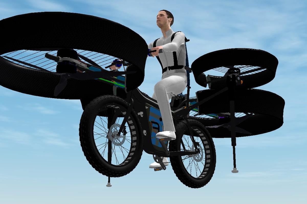
1 MW
I’m convering this too-small-for-me bike into a mid drive with these ingredients:
https://imgur.com/gallery/BhQWNKC
Vesc6
https://trampaboards.com/vesc-6-mkiv-in-cnc-t6-silicone-sealed-aluminium-box-with-genuine-xt90-connectors--vedder-electronic-speed-controller-trampa-special-p-27536.html
(Maybe should go bigger)
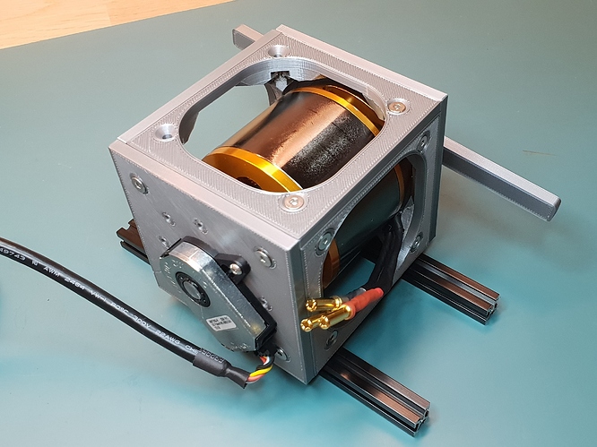
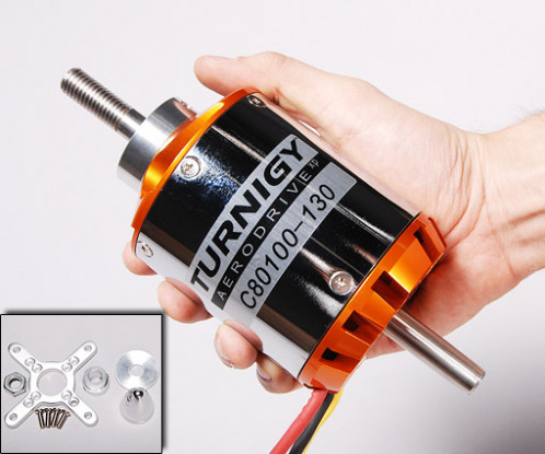
https://www.altitudehobbies.com/collections/leopard-airplane-motors/products/leopard-8072-11t-160kv-brushless-airplane-motor
(Maybe I should go bigger. Have to figure the gear ratio then kv)
(100) 26650 A123 green iron cells
https://lunacycle.com/luna-sur-ron-belt-drive-upgrade-kit/
1)
I plan to fill the triangle with a potted block that will include the cells, a motor mount plate, and a shaft on the same plane as the plate to add two pulleys for a double gear reduction drive
Kinda like this
https://lunacycle.com/luna-wolf-v2-52v-battery-pack/
but bigger and will include the motor mount, extra shaft, and some mounting rods I’ll thread so it will attach to the seat and downtube with some plastic plates I’d cast. The interface between the the block and down and seat tube..id add a couple subsequently softer layers to the block I’d paint on.
2)
I figured I could do a single speed chain drive on the right side of the bike as usual and the left side of the bike would have the two belts with one attaching to the rear wheel brake rotor mount. Not thrilled on modifying to attach to the brake rotor mount but seems ok and will figure a one way clutch on the extra shaft
3)
I’m also adding mounting rods to the casting/potting I can thread and attach to compete triangle to the frame by plastic plates I’d cast..one for four bolts attaching to the seat tube and two plates totaling 8 bolts for attaching to the downtube.
https://imgur.com/gallery/BhQWNKC
Vesc6
https://trampaboards.com/vesc-6-mkiv-in-cnc-t6-silicone-sealed-aluminium-box-with-genuine-xt90-connectors--vedder-electronic-speed-controller-trampa-special-p-27536.html
(Maybe should go bigger)
https://www.altitudehobbies.com/collections/leopard-airplane-motors/products/leopard-8072-11t-160kv-brushless-airplane-motor
(Maybe I should go bigger. Have to figure the gear ratio then kv)
(100) 26650 A123 green iron cells
https://lunacycle.com/luna-sur-ron-belt-drive-upgrade-kit/
1)
I plan to fill the triangle with a potted block that will include the cells, a motor mount plate, and a shaft on the same plane as the plate to add two pulleys for a double gear reduction drive
Kinda like this
https://lunacycle.com/luna-wolf-v2-52v-battery-pack/
but bigger and will include the motor mount, extra shaft, and some mounting rods I’ll thread so it will attach to the seat and downtube with some plastic plates I’d cast. The interface between the the block and down and seat tube..id add a couple subsequently softer layers to the block I’d paint on.
2)
I figured I could do a single speed chain drive on the right side of the bike as usual and the left side of the bike would have the two belts with one attaching to the rear wheel brake rotor mount. Not thrilled on modifying to attach to the brake rotor mount but seems ok and will figure a one way clutch on the extra shaft
3)
I’m also adding mounting rods to the casting/potting I can thread and attach to compete triangle to the frame by plastic plates I’d cast..one for four bolts attaching to the seat tube and two plates totaling 8 bolts for attaching to the downtube.