You are using an out of date browser. It may not display this or other websites correctly.
You should upgrade or use an alternative browser.
You should upgrade or use an alternative browser.
Serious FOCer (84V VESC 6 based controller)
- Thread starter shaman
- Start date
shaman
1 kW
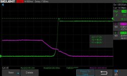
Well let's say i'm getting it dialed in. I'll throw it on my ebike with a 20s battery in a coupe of days. Special thanks to @zombiess for helping with the gate drive strength tuning.
shaman
1 kW
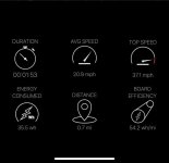
Trial run around the block. Went up to 37mph
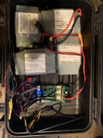
janky ebike I threw together to test stuff. 10s batteries in series for a 20s battery.
Well I took it around the block a bit. 60A FOC starting at 82ish volts. No issues. I'll be taking it out on a straight road tomorrow when its daylight. Let's see if I can hit 40mph!
shaman
1 kW
Kits are still being considered for a few reasons. I might do a limited production run of some kits after beta testing. The idea is to test out production and customer support for that sort of thing.
Will there be a higher Voltage version for Motorcycles?
QS offers a 20kw peak motor integrated inside a 13 inch wheel, perfect for a "vespa like" electric city motorcycle.
I was wondering If i could use your board but change the FETs and Capacitors to accommodate a 26s Lipo.
I am currently looking for a controller and couldn't find anything so I guess DIY or something like you are designing is my only option
shaman
1 kW
@Kalzifa this controller will only do 20S as advertised. Trying for 26s would call for a complete redesign and not just changing out FETs and caps. You might be interested in galp's BESC. It is made for higher voltage
bww129
100 mW
It took a few days to read through all your FOCing FOCer threads  (great name choice) but it was well worth it to see such a great effort documented. Kudos for the multiple iterations and keeping with it this long! You must not have any kids and enjoy working long hours :wink:
On a technical note, it looks like this design uses 2512 size current sense resistors, and the ones you've spec'd look like the beefy all metal kind that can probably handle up to about 150A without derating. Have you considered the effects of continuous high phase currents on the solder joints of these components? I only ask because I've done short circuit testing on a 12V 35A brushed DC controller of my own design and was able to vaporize the solder joints on some 1mohm 2512 current sense resistors before a 35A inline fuse blew. There had to have been at least a few hundred amps flowing to get it to do that! No mosfet failures either. The current density going into the 2512 pads will be very high for the currents you're dealing with. It might be worth using two resistors in parallel or going to a bigger package.
On a technical note, it looks like this design uses 2512 size current sense resistors, and the ones you've spec'd look like the beefy all metal kind that can probably handle up to about 150A without derating. Have you considered the effects of continuous high phase currents on the solder joints of these components? I only ask because I've done short circuit testing on a 12V 35A brushed DC controller of my own design and was able to vaporize the solder joints on some 1mohm 2512 current sense resistors before a 35A inline fuse blew. There had to have been at least a few hundred amps flowing to get it to do that! No mosfet failures either. The current density going into the 2512 pads will be very high for the currents you're dealing with. It might be worth using two resistors in parallel or going to a bigger package.
shaman
1 kW
I appreciate you taking the time to read! So both...no kids + long hours. This is for sure my passion.
The Little FOCer hasn't shown issues with the 2512 sense resistors and I've taken it up to 90 amps. However I did switch to size 3920 for anything larger for up to 150A. Anything more will require hall effect sensors or paralleled sense resistors like I did for the Cheap FOCer 2.
The Little FOCer hasn't shown issues with the 2512 sense resistors and I've taken it up to 90 amps. However I did switch to size 3920 for anything larger for up to 150A. Anything more will require hall effect sensors or paralleled sense resistors like I did for the Cheap FOCer 2.
shaman
1 kW
I know I've given some timelines and expectations that didn't turn out to be true or were unrealistic to begin with. Here's some of the main issues contributing to the hold up on this stuff.
1. I can't do this full time. My hours have been split between my full time job (electrical engineer), my part time job (military), and various emergencies related to family. This doesn't leave nearly as much time as I want to develop this stuff.
2. I'm still learning. Understanding proper layout and operation of power electronics takes a lot of time to understand. People like @zombiess have been trying to bring me up to speed on good layout and what factors are important in power stage design. Unfortunately, I've been slow to learn and understand the physics behind Maxwell's Equations that need to be considered in good layout... but I'm finally starting to understand some of it.
3. The VESC firmware is picky about the power stage involved. In my development and testing I've discovered that the effectiveness of the VESC motor detection and control algorithms depend on the rise/fall times of the MOSFET switching. For whatever reason, the official VESC hardware switches in 50ns or less. This is unnecessarily fast for 50kHZ or less switching frequencies. Power stages with more reasonable switching times (like 150ns or more) then suffer since the software/firmware was written around this crazy fast power stage hardware. I have raised this issue with the VESC firmware developers and they have claimed to be working on a resolution. Switching in 50ns or less with my hardware causes higher dV/dt spikes and MOSFET self turnon that I do not want to accept.
4. Finalizing the design may take more time. Since gaining more understanding of proper power stage layout, I've played around with different designs than what you've seen on this thread and than what I've prototyped. Designs that have better layout, better thermal management, have 12% smaller footprint, and are more easily scalable while still being in the same class of cost.
In the end, I do not want to release an inferior product. It's better that I reset expectations of a timeline here in favor of developing the best product I possibly can. During these months of COVID lockdown, I've invested about 10,000USD in to remodeling my garage into a proper shop so that I can proceed with good development and proper testing. The Little FOCer is first up in the que of work. I want to finalize this design which will in turn allow for a more powerful version to easily be produced since it's only more or less a swap for TO-247 MOSFETs.
zombiess
10 MW
It's unfortunate that you don't have more free time. I could help you get up to speed much quicker in understanding the meaning of Maxwells Equations. There are many analogies to be made to help you digest it. IMO it's pointless to learn the math first vs understanding the ramifications. Once you get a grasp on how it works, the math just kinda falls into place, even if you aren't very good at manipulating it (like me). You just need to be able to read the equations and relate the pieces to what physically happens and IMO that's waaaay easier once you know what the math represents. Meaning first, math later. Of course if you are like Terrance Tao, Bernhard Riemann or Herman Minkowski, then by all means, go nuts and learn the math first.
EE works gets so much simpler when you can mentally visualize the magnetic fields w.r.t. trace inductance on your layout as you design.
I got so much cool stuff to talk about no one else cares about :lol:
EE works gets so much simpler when you can mentally visualize the magnetic fields w.r.t. trace inductance on your layout as you design.
I got so much cool stuff to talk about no one else cares about :lol:
motordriver111
1 µW
- Joined
- Jul 15, 2020
- Messages
- 2
Hey shaman,
I donated you from paypal like u said.
Could you share the kicad and bom files to me please
I am building my own powerful e-bike and i am very excited for this.
Thanks !
I donated you from paypal like u said.
Could you share the kicad and bom files to me please
I am building my own powerful e-bike and i am very excited for this.
Thanks !
shaman
1 kW
@motordriver111 I appreciate the donation but unfortunately I will not be sharing the design files. If you would like an open source controller where I share everything, please see my Cheap FOCer 2 (CFOC2) thread. All files are available on github for the CFOC2,
shaman
1 kW
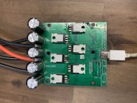
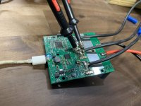
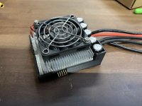
Still making progress however slow it is.
I've got the materials for a beta unit batch and I've been analyzing performance with different MOSFETs. So far so good. Thermal performance is good and I've tested with and without the optional fan. I'm still working on the enclosure design but it's simple.
shaman said:I'm still working on the enclosure design but it's simple.
Loooking good! More VESC-like; less E-bike-like. Is this the definitive layout ? What are the exact dimensions ?
shaman
1 kW
Yeah it’s more compact than typical ebike controllers and the power density is far higher. It’s half the size of a cheap “1000W, 48V” controller. Still distinct from most VESC based stuff due to the through hole MOSFETs and not super expensive CNCed enclosures
Dimensions are 83.8 x 72.1 x 42 (mm) with the fan. About 30mm tall without the fan.
Dimensions are 83.8 x 72.1 x 42 (mm) with the fan. About 30mm tall without the fan.
shaman said:Dimensions are 83.8 x 72.1 x 42 (mm) with the fan. About 30mm tall without the fan.
Tricky size for a cheap szomk box - maybe that statement about expensive cnced enclosures will change...
How about the firmware issue related to high switching frequencies ? Do you have a link to the dev thread ? I'll start looking into it. A clean solution should be a routine that auto selects optimal timing according to hw specs after a few test loops.
shaman
1 kW
qwerkus said:Tricky size for a cheap szomk box - maybe that statement about expensive cnced enclosures will change...
Not going for the extruded enclosure. Just the extruded heat sink like in the photo and the whole thing capped by a plastic top. You can kind of see that in the last pic from my previous post. Still a low cost solution since the heat sinks are generic (like the szomk stuff) and the plastic portion can be 3D printed in low volume. If/when volumes go up, then the plastic cap can become injection molded or cast aluminum. I'm also going to investigate potting which would also do well to protect the controller.
So the issues I was having related to rise/fall time of the MOSFETs are believed to be related to the low-side current sensing that I'm implementing. I've been able to mitigate this by switching fast enough to get good motor detection/control but not so fast that dV/dt transients start wreaking havoc. I'm making low side sensing work for this design for cost reasons but I won't be doing it for future designs.
mxlemming
100 kW
- Joined
- Jul 17, 2020
- Messages
- 1,120
zombiess said:It's unfortunate that you don't have more free time. I could help you get up to speed much quicker in understanding the meaning of Maxwells Equations. There are many analogies to be made to help you digest it. IMO it's pointless to learn the math first vs understanding the ramifications. Once you get a grasp on how it works, the math just kinda falls into place, even if you aren't very good at manipulating it (like me). You just need to be able to read the equations and relate the pieces to what physically happens and IMO that's waaaay easier once you know what the math represents. Meaning first, math later. Of course if you are like Terrance Tao, Bernhard Riemann or Herman Minkowski, then by all means, go nuts and learn the math first.
EE works gets so much simpler when you can mentally visualize the magnetic fields w.r.t. trace inductance on your layout as you design.
I got so much cool stuff to talk about no one else cares about :lol:
I for one would very much like to hear/talk about this. I have the math ability, I don't have years of elec eng experience. I do pretty well visualising stress fields in solids, predicting flow patterns etc...
I bet Shaman would love to know too.
zombiess
10 MW
mxlemming said:I for one would very much like to hear/talk about this. I have the math ability, I don't have years of elec eng experience. I do pretty well visualising stress fields in solids, predicting flow patterns etc...
I bet Shaman would love to know too.
This is my goto reference video for electromagnestism
https://youtu.be/9Tm2c6NJH4Y
You can get a free physics education by watching all his videos. I need to go through them all again myself as it's been several years and i need a refresher.
To break down the math:
http://www.maxwells-equations.com/m/index.php
That video and website are what made it click for me, after many many hours of study. Several years ago I coultdnt even algebra, so i had to re-learn that. I still suck at manipulating math, but thats what matlab and Wolfram alpha are good for.
Similar threads
- Replies
- 11
- Views
- 1,812
- Replies
- 55
- Views
- 14,054
- Replies
- 182
- Views
- 18,361
- Replies
- 66
- Views
- 12,573


