Serious FOCer (84V VESC 6 based controller)

zombiess said:
mxlemming said:
I for one would very much like to hear/talk about this. I have the math ability, I don't have years of elec eng experience. I do pretty well visualising stress fields in solids, predicting flow patterns etc...

I bet Shaman would love to know too.

This is my goto reference video for electromagnestism
https://youtu.be/9Tm2c6NJH4Y

You can get a free physics education by watching all his videos. I need to go through them all again myself as it's been several years and i need a refresher.
This is pretty basic stuff... 48minutes, it's painfully slow :confused:
I actually don't like youtube tutorials of stuff, they are almost invariably intolerably slow and basic. And I'm not especially patient.

zombiess said:
To break down the math:
http://www.maxwells-equations.com/m/index.php

Nice summary, this is great. Been a few years since I studied the calculus, but when it's neatly put into a few neat lines like this, it comes back fast!

Over in my other thread I am struggling to understand the need for isolated gate drives and gate drive power supplies. It seems to me that they should not be a requirement unless your system is so large that there are unavoidable large gaps between phases or unavoidably large connections between power stage and the uController. Clearly this is the case if you have stacks and stacks of paralelled IGBTs with multiple gate drivers/phase, like you're making an electric car or inverter for a wind turbine, but for our little <10kW inverters... The max resistance across the ground plane of my PCB calculates as <1mohm before reinforcing with copper sheet, so for even 200A, that's just 0.2V, which won't really affect anything. Not even the logic.

Inductive turn on... Much trickier to come to terms with, but again, with small loops, keeping all the logic traces routed cleanly above a solid ground plane, and keeping the gate drive traces routed next to their return path (switch node or ground plane), only crossing power traces perpendicularly so that the cross product of the trace and the magnetic field around the high current path is zero it should just all work out with the inductive spikes canceling on the send and return path, the capacitances of the gates and gate resistors damping etc...

Then there's miller turnon - the gate-drain capacitance charging and thus bouncing the gate-source capacitance voltage... Am I right in thinking that this becomes an issue when VddxCgd is not << VthresholdxCgs such that the rapid swing (which cannot be absorbed through the gate driver/resistors) causes the gate potential to exceed the threshold voltage of the FET?

Or did I just get lucky on a not huge power inverter?

I certainly did not get lucky on my first ever inverter I attempted to build; breadboard with jumper wires for ground connections... the second one I made (https://photos.app.goo.gl/aShDJQYV39dip2ui9) was a whole lot better, but still had a 3 inch square return loop on the gate drives. That one basically worked, but I kept murdering FETs with losing synch and over volting them into avalanche, or creating buck arrangements through the motor that dumped vast and unmeasured numbers of amps through... everything... I never came to terms with why this killed gate drives as well, but it did. I also didn't believe in ceramic capacitors, so the power lines were full of spikes. I didn't believe in them because attaching those huge leaded discs using extension wires seemed to do very little :lol: .

That's a year ago though. blowing little expensive things up makes you think harder and learn fast.

Incidentally, I created a nice example oscilloscope trace yesterday of what happens when your motor loses synch (spun up a bike wheel and unplugged a hall sensor while running). I guess this is why you need 100V fets for a 60V drive. Those little ringy things on the square edges take up ~10V, then you need a few V of room (5? 10?)for any regen braking to push the current back into your battery, then you need some headroom to allow your OVP to occur before things die without always tripping erroneously(another 10?) then you're up to 85V and therefore need 100V FETs...
https://photos.app.goo.gl/aShDJQYV39dip2ui9
The rotor (/and bike wheel/and KE of you rolling down a hill/...) energy gets erratically converted into current which ultimately ends up on the power rail boosting the power rail voltage up and up until either something clamps it or the inverter turns off (here I programmed a comparator on the Vbus line to cut timer1 PWM output as soon as voltage exceeds 30V, so it trips before killing everything.
 
mxlemming said:
This is pretty basic stuff... 48minutes, it's painfully slow :confused:
I actually don't like youtube tutorials of stuff, they are almost invariably intolerably slow and basic. And I'm not especially patient.

Yup, his videos are slow paced on purpose, but if you are just reviewing or learn fast, watch them on high speed. It's often good to review the basics. I don't use this stuff every day, so the memories fade. Learning is not often a once and done deal.


Over in my other thread I am struggling to understand the need for isolated gate drives and gate drive power supplies. It seems to me that they should not be a requirement unless your system is so large that there are unavoidable large gaps between phases or unavoidably large connections between power stage and the uController. Clearly this is the case if you have stacks and stacks of paralelled IGBTs with multiple gate drivers/phase, like you're making an electric car or inverter for a wind turbine, but for our little <10kW inverters... The max resistance across the ground plane of my PCB calculates as <1mohm before reinforcing with copper sheet, so for even 200A, that's just 0.2V, which won't really affect anything. Not even the logic.

Isolation reduces noise and increases safety. You don't always need it, but using it reduces the probability of negative consequences.

Inductive turn on... Much trickier to come to terms with, but again, with small loops, keeping all the logic traces routed cleanly above a solid ground plane, and keeping the gate drive traces routed next to their return path (switch node or ground plane), only crossing power traces perpendicularly so that the cross product of the trace and the magnetic field around the high current path is zero it should just all work out with the inductive spikes canceling on the send and return path, the capacitances of the gates and gate resistors damping etc...

In theory, but current doesn't always follow the return path you think it should. Start slamming hundreds of amps back and forth in 100ns and you end up generating all kinds of frequencies, not all of them behave the same. The closer you approach an impulse response, the more frequencies you generate. Does everything in your circuit behave the same at all frequencies? Chances are that's a no as capacitive coupling and inductive coupling come to mind. Even when doing isolation the amount of capacitance across the barrier can matter. Noise mitigation is why generally you only switch as fast as you need to, not as fast as you can.

Then there's miller turnon - the gate-drain capacitance charging and thus bouncing the gate-source capacitance voltage... Am I right in thinking that this becomes an issue when VddxCgd is not << VthresholdxCgs such that the rapid swing (which cannot be absorbed through the gate driver/resistors) causes the gate potential to exceed the threshold voltage of the FET?

I'd have to go read up on the physics again to answer that; how about you read up on it and explain it to me, homework we both learn from :mrgreen: I do know that if you clamp the gate and provide a low impedance path, you minimize the probability of Miller effect turn on.

Or did I just get lucky on a not huge power inverter?
At low power you can get away with a lot of bad practices.

I certainly did not get lucky on my first ever inverter I attempted to build; breadboard with jumper wires for ground connections... the second one I made (https://photos.app.goo.gl/aShDJQYV39dip2ui9) was a whole lot better, but still had a 3 inch square return loop on the gate drives. That one basically worked, but I kept murdering FETs with losing synch and over volting them into avalanche, or creating buck arrangements through the motor that dumped vast and unmeasured numbers of amps through... everything... I never came to terms with why this killed gate drives as well, but it did. I also didn't believe in ceramic capacitors, so the power lines were full of spikes. I didn't believe in them because attaching those huge leaded discs using extension wires seemed to do very little :lol: .

Good learning experience for sure. I had someone experienced hold my hand through my first real design and did everything I was told (when I finally shut up and listened to reason), the end result was my first inverter design worked up to +15kW peaks on 125V.

That's a year ago though. blowing little expensive things up makes you think harder and learn fast.
You'll never stop blowing stuff up because humans make errors. I recently made a boost converter, put a diode in backwards, 2 $10 IC's later I found the issue. Then the 3rd one didn't work and I realized I had a schematic error on that same diode and made the connection to the wrong side of a capacitor. Bodged it, but too late, 3rd $10 IC was toast. I reviewed that schematic countless times prior to prototype PCB production and still missed it. It's just part of the game. $30 of oops in a few hours, waiting for a Digikey to deliver the replacements which should work.

Incidentally, I created a nice example oscilloscope trace yesterday of what happens when your motor loses synch (spun up a bike wheel and unplugged a hall sensor while running). I guess this is why you need 100V fets for a 60V drive. Those little ringy things on the square edges take up ~10V, then you need a few V of room (5? 10?)for any regen braking to push the current back into your battery, then you need some headroom to allow your OVP to occur before things die without always tripping erroneously(another 10?) then you're up to 85V and therefore need 100V FETs...
https://photos.app.goo.gl/aShDJQYV39dip2ui9
The rotor (/and bike wheel/and KE of you rolling down a hill/...) energy gets erratically converted into current which ultimately ends up on the power rail boosting the power rail voltage up and up until either something clamps it or the inverter turns off (here I programmed a comparator on the Vbus line to cut timer1 PWM output as soon as voltage exceeds 30V, so it trips before killing everything.

Congrats on finding a failure mode. A good design takes issues like this into consideration. I've seen many people kill controllers from loss of sync, which can cause a high current transient or shoot through event. I've had desync's happen to me regularly during control loop tuning, but my hardware was fault tolerant and shut down. What happens if a gate drive loses power during operation, can you detect it, will it UVLO? Will it output a fault? How do you handle that fault? Should your fault signal be active high or active low? What happens if you disconnect the traction pack during operation, such as if a fuse popped? Etc.

Power cycle it and continue on with no damage. You can design a fully isolated gate drive for about $60 of parts, how much do you value your time?

Go study the Axiom schematic, it's a free goldmine of power electronics basics done by an aerospace engineer.
Fault detection needs to be fast and done in hardware if you want to create a good build. Over voltage and over current detection are pretty standard practices and done with comparators. Hardware is your first line of defense and it's often fast enough to prevent failure. The fault output from hardware should then shutdown the software side which is much slower to react.

The Axiom schematic shows you how to do this, but you'll need to convert the input to single ended most likely. A good schematic is only half the battle, proper layout practices are the other half. Isolating each gate drive through it's own power supply minimizes the transmission of noise. Yes, this method is more expensive, but it's almost mandatory > 10kW IMO.
 
This might be an unpopular opinion, but I'm not so impressed by the axiom. In terms of what we're discussing, there's very little to learn - they've just boshed in 3x 2SP0115T2A0 isolated gate driver modules (modules nor chips), with all the power supply, isolation... Etc...) and 3 infineon igbt modules which basically solve all the hard bits as far as I can see. Those gate drives EACH cost 3x my controllers target BoM, and the igbts 6x. That's 27x the cost before looking at the other bits, so not really my cup of tea and not really applicable top most of pour evokes and skate boards.

Their addition of mtpa to the vesc is great.

Hardware fault detection for the win. This is something vesc lacks, and the main reason I've run with the f303 chip - with about 20 lines of code I've got embedded but hardware over voltage, and over current on all 3 phases. I was thinking earlier about the time taken to shut down under software. If you can shut down as soon as (well a few clock cycles into) the ADC conversion complete interrupt fires, how much higher can the bus voltage go? 1pwm cycle and 1 dump of inductive energy into the capacitors. How much is that?

Equate 1/2LI^2 and 1/2C(V2^2-V1^2) and I got 10V for my 55V bus, 68uH motor, 100 amps at the failure point and 560uF caps.

So I thought "interesting. Maybe it needs a comparator".

But does it help? I'm not sure it does, assuming your MCU hasn't crashed, since the inductive energy will still be dumped onto the power rail through the body diodes anyway.

Very nice for dev though, because I crash the MCU most times i program it, and break points in your code essentially have the same effect as crashing it.
 
Honestly, the most impressive vesc I've seen is probably Galp's, it's so tidy, compact and... 30kW now? His Giant Glory testing through the woods vid was what started me on my ebike project.

Now if only he/shaman would just finish their damned projects and start selling them I might not have bothered making my own PCB.

:p
 
zombiess said:
I'd have to go read up on the physics again to answer that; how about you read up on it and explain it to me, homework we both learn from :mrgreen: I do know that if you clamp the gate and provide a low impedance path, you minimize the probability of Miller effect turn on.

https://www.infineon.com/dgdl/Parasitic_Turn-on_of_Power_MOSFET.pdf?fileId=db3a30431ed1d7b2011eee756cee5475

As I thought, according to infineon. You can basically take my explanation above as correct I think. Just the ratio of the Cgd to Cgs and the threshold voltage matter at high switching speeds.
 
This doesn't account for the gate plateau voltage but I think that improves the situation rather than make it worse.
 
mxlemming said:
https://www.infineon.com/dgdl/Parasitic_Turn-on_of_Power_MOSFET.pdf?fileId=db3a30431ed1d7b2011eee756cee5475

That is a killer paper on Miller Effect, better than my existing references! Stored it in my notebook for future reference, thank you.

mxlemming said:
This might be an unpopular opinion, but I'm not so impressed by the axiom. In terms of what we're discussing, there's very little to learn - they've just boshed in 3x 2SP0115T2A0 isolated gate driver modules (modules nor chips), with all the power supply, isolation... Etc...) and 3 infineon igbt modules which basically solve all the hard bits as far as I can see. Those gate drives EACH cost 3x my controllers target BoM, and the igbts 6x. That's 27x the cost before looking at the other bits, so not really my cup of tea and not really applicable top most of pour evokes and skate boards.

Axiom is purposefully designed as a basic high reliability controller, done correctly with a public schematic. That is what makes it so unique. It is a foundation. When experienced designers choose to use off the shelf solutions, the question to ask is what drove that design decision. Every single part on its design has been carefully vetted based on what I know about the members of the team. I doubt there was any "boshing" involved.
 
The Infineon paper's not the most comprehensive, but it is hella concise and to the point, for which I like it a lot. I read TI, On Semi, various others, and lost the will to live amidst the pointless nitpicking and obfuscation.

I'm sure Axiom know what they're doing, but if I boshed this https://cache.industry.siemens.com/dl/files/916/11886916/att_32224/v1/MM440_OPI_engl_B1.pdf
into a box, and said "Look 100kW inverter", I would probably have a very robust solution for an inverter, but wouldn't really have designed an inverter. Likewise, they may have made a very wise choice to use the 68$ gate drive module, but they didn't design a gate driver...

Guess I should start refining sand to get my silicon wafers.
 
shaman said:
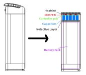
Not going for the extruded enclosure. Just the extruded heat sink like in the photo and the whole thing capped by a plastic top. You can kind of see that in the last pic from my previous post. Still a low cost solution since the heat sinks are generic (like the szomk stuff) and the plastic portion can be 3D printed in low volume. If/when volumes go up, then the plastic cap can become injection molded or cast aluminum. I'm also going to investigate potting which would also do well to protect the controller.

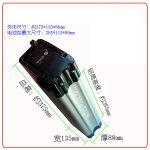
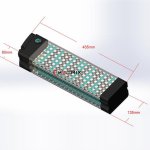
Hey shaman, I may have found a clean casing solution for your controller. On many cheap ebikes, manufacturer use so called "silver fish" aluminium battery boxes placed behind the seatpost. While the plastic top and bottom cover are really crappy, the box itself is pretty decent. All you have to do is cut custom cover plates, and you have a very decent battery case. The round grove on on side is pretty handy if you chose to use the box against the bikes lower tube.

Now the interesting part: those boxes come in various sizes. The two most common beeing 110*75mm (91*72 internal) and 135*88 (115*80 internal). Here some pics of the larger model:
5.jpg
4.jpg

Now if one solders the capacitors on the other side of the pcb of your controller, it should be possible to bolt the board directly onto a custom made top cap, with the fets facing outside. You can always use finned aluminium as cover, which would make a perfect cooling solution, while the body of the controller stays protected inside the box. You see what i mean ?

6.jpg

If you manage to narrow the board to around 70mm width max, you could even fit it into the smaller 110*75mm box!
 
@qwerkus that's a pretty cool concept actually. I've designed the board in a way so that caps and connectors can be soldered on the opposite sides to that this kind of thing is possible.
 
Update:

It's been a while but the project is not dead! Beta testing has been going well and I'm moving forward with a manufacturer for the Little FOCer.

Getting stuff manufactured takes a while. Especially to quality check everything. I’ve got samples from the manufacturer on their way. The samples are in Alaska and I’m in Texas. So hopefully not long now. I’ll be putting these samples under the microscope and checking everything. After these checks are conducted and any mistakes are rectified, then the rest will be produced.

I’ve finally got a decent ebike built and running. I’m using it to test my controllers to include the Little FOCer. I’m running the Little FOCer on a 16S battery at 120A motor and 60A battery. The way I’m handling the cooling is really good so that’s why I can run it at that high of current. I’m using a MXUS V3 hub motor. Everything runs smooth and fast. 45mph doesn’t sound fast but sure seems like it on a bicycle.

I’ll be reorganizing my threads when I have the Big/Serious FOCer prototype functioning. That’s a new criteria for me. No more new threads on new products until a prototype is in hand and functioning. The Big/Serious FOCer prototype is in-hand and I’m going through the initial debug and analysis of it albeit slowly. This level of power needs special care.
 
So I've been following this post on and off for 2 years now.. really like what youre doing with this.

When can we get the schematics for this so called "open source" board? You say its open source but there is no source code/schematics/pcb designs to be found, so I assume you're still collecting donations before releasing. But c'mon 2 years to get the schematic is a very long time.

Sent from my SM-G970F using Tapatalk

 
Thanks for your on going interest! I need to update this thread. Much progress has been made

The hardware of my commercial products will not be open sourced. The cheap FOCer series is my contribution to the world of open source hardware. You can find the source code of both the little FOCer and cheap FOCer in the official vesc GitHub repo

2 years is what it takes for me doing this part time, self funding, and properly testing this hardware next to a full time job and family. Hopefully progress can happen faster if this can be my full time job
 
Hi Everyone. Just wanted to post that basic PAS support has FINALLY been added to the main vesc controller code branch: https://github.com/vedderb/bldc/pull/243
Actually 5 months old news, but still: I think that's one huge step in favor of shaman's serious focer. Torque sensor are still missing, and a basic way to set up assist level.
 
https://www.makerspev.com/collections/frontpage
https://customwheel.shop/

This is what I got out right now. The Little FOCer is a lot of power in a small package. Now fighting the chip shortage to keep it alive. My other more powerful designs are being released as the Tronic Series of controllers.
 
I just spent 5-6 hours reading through this complete thread, and the other 2 (CheapFOCer, etc.).
I found it very educational and entertaining and, just like with a good book, I kept myself from jumping to the last page to see how it all ends (or rather, the current status). Thanks for this very informational blog!

Now I got to the end and find out (if I'm not mistaken) that there will be no opensource hardware for the DRV8353 version (or any other version that can handle >50V battery), is that correct? And the commercial products cost 300-500€ :shock:
I'm not as surprised as some, to find the initial "40-50$" estimate skyrocket like that, but I was sort of hoping to save some money vs. the official VESC Trampa products... I do recognize though that you've put tons of time+money into this and need to get some kind of payback for it.

I'm currently building an outdoor robot (I have lots of ideas for applications, some of the simplest being outdoor sweeping or mowing very large lawns) but first I need to get a strong (need >1kN pull force) but finely navigatable mechanical platform working that I'm satisfied with) with 2 "48V/500W" geared wheelbarrow hub motors. After finding the BLDC controller I was using (20€ 400W Amazon ones, thought they would be ok for testing without load, but the wheels keep cogging and not starting up reliably and the controllers overheating) was not suitable, I started googling opensource BLDC controllers, learned about VESC in general and delightedly ordered a dual flipsky 6.7 (advertised at 60V/70A per channel) on BG, which at 230€ was already not cheap for my budget (but still half what Trampa would have cost). While waiting for delivery I worryingly discovered several posts about broken DRV8302, while looking for more info only then learned that the "60V" limit is not safe for the 48-54V battery I plan to use (Pylontech US2000). I also found an Intel support forum posting (https://e2e.ti.com/support/motor-drivers-group/motor-drivers/f/motor-drivers-forum/1037205/drv8302-failure-of-drive-chip-when-running) stating that they recommend using only half the 60V limit as battery voltage --> 30V. I'm pretty much fixed on my battery choice, there are no good alternatives that I know of. So then I was hoping to find an affordable controller which uses the 100V driver chip DRV8353 and came here. But no way can I spend another 700€ for 2 controllers now :-(

So my hope is that even though my battery voltage (which will usually be between 47 and 51V during operation, while not being charged, 54V is the full-charge voltage) is rather close to the 60V voltage-of-death, since in my application I won't be running the motors very fast (probably never over 1000 ERPM) and hardly any coasting or braking (and only with low currents like <10A), that I won't have the deadly spikes that have killed may people's DRV chips. If I'm wrong, well, I guess I'll be forced to buy a pair of 100V controllers, whatever the cost.
 
arnolde said:
I just spent 5-6 hours reading through this complete thread, and the other 2 (CheapFOCer, etc.).
I found it very educational and entertaining and, just like with a good book, I kept myself from jumping to the last page to see how it all ends (or rather, the current status). Thanks for this very informational blog!

Now I got to the end and find out (if I'm not mistaken) that there will be no opensource hardware for the DRV8353 version (or any other version that can handle >50V battery), is that correct? And the commercial products cost 300-500€ :shock:
I'm not as surprised as some, to find the initial "40-50$" estimate skyrocket like that, but I was sort of hoping to save some money vs. the official VESC Trampa products... I do recognize though that you've put tons of time+money into this and need to get some kind of payback for it.

I'm currently building an outdoor robot (I have lots of ideas for applications, some of the simplest being outdoor sweeping or mowing very large lawns) but first I need to get a strong (need >1kN pull force) but finely navigatable mechanical platform working that I'm satisfied with) with 2 "48V/500W" geared wheelbarrow hub motors. After finding the BLDC controller I was using (20€ 400W Amazon ones, thought they would be ok for testing without load, but the wheels keep cogging and not starting up reliably and the controllers overheating) was not suitable, I started googling opensource BLDC controllers, learned about VESC in general and delightedly ordered a dual flipsky 6.7 (advertised at 60V/70A per channel) on BG, which at 230€ was already not cheap for my budget (but still half what Trampa would have cost). While waiting for delivery I worryingly discovered several posts about broken DRV8302, while looking for more info only then learned that the "60V" limit is not safe for the 48-54V battery I plan to use (Pylontech US2000). I also found an Intel support forum posting (https://e2e.ti.com/support/motor-drivers-group/motor-drivers/f/motor-drivers-forum/1037205/drv8302-failure-of-drive-chip-when-running) stating that they recommend using only half the 60V limit as battery voltage --> 30V. I'm pretty much fixed on my battery choice, there are no good alternatives that I know of. So then I was hoping to find an affordable controller which uses the 100V driver chip DRV8353 and came here. But no way can I spend another 700€ for 2 controllers now :-(


So my hope is that even though my battery voltage (which will usually be between 47 and 51V during operation, while not being charged, 54V is the full-charge voltage) is rather close to the 60V voltage-of-death, since in my application I won't be running the motors very fast (probably never over 1000 ERPM) and hardly any coasting or braking (and only with low currents like <10A), that I won't have the deadly spikes that have killed may people's DRV chips. If I'm wrong, well, I guess I'll be forced to buy a pair of 100V controllers, whatever the cost.

Go look at the MP2 ESC thread on this forum. Completely open source, and several people have built them already, for actual BoM costs of about 60$ each. Warning though, your hundreds of dollars you pay people like Shaman are surprisingly well spent when you start soldering your own ones together and realise just how long it takes and how easy it is to make mistakes.
 
Hey there it's been a while since I've posted. So yeah you can find the Little FOCer at the links below. It's what the serious focer became over time.

https://www.makerspev.com/collections/frontpage
https://customwheel.shop/en/

The Cheap FOCer 2 is kind of hard to make now because of the chip shortage so I started the Cheap FOCer 3 (CFOC3). The CFOC3 has design improvements as well as being designed with components actually in stock, It's in testing right now with success both in onewheel type and typical traction type applications. Outperforms the CFOC2 in every way.

https://forum.esk8.news/t/cheap-focer-3-open-source-low-cost-vesc-6-based-esc-in-development/67432
 
No. But that's why I'm working on the CHEAP FOCer. As to have a lower cost option.
 
@shaman would you mind answering my question (asked 2w ago) on the CFOC3 esk8 forum, regarding a source for the CFOC3 current hardware details, schematics, BOM etc.?

Thanks :)
 
Yep! Done.

I'll post the answer here too. I’d rather wait until the github release before showing schematics. Nothing is ready to be presented. Let me clean them up and such. before I do.

The layout is similar to the CFOC2.
 
Back
Top