TSDZ2 mid drive with 860C, 850C or SW102 displays only -- Flexible OpenSource firmware (Casainho code only)

jeff.page.rides said:
This is a copy of a reply to an email I received asking about the displays and firmware available for the TSDZ2.
I thought I would share my opinion on the different versions of firmware and the different displays

Hi Lee,

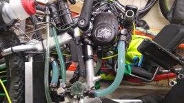
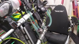
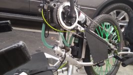
There are four different displays with three different firmware programs available for the TSDZ2. The 860C display only works with V1 but is by far the best display. The 850C display works with V1 and V19 but you can’t read it in the sun. The LCD3 display works with V19 and V20 and is a good display that works in the sun, but has to be disassembled to flash. The VLCD5 is a very limited display that works with the stock firmware and V20. But to change settings or view different information with V20 is very difficult. But the display doesn’t need to be flashed, only the motors need to be flashed and it’s easy and very quick to flash with different settings and works well with V20.

Version 1 is very refined but very complex and difficult to set up and to get working correctly. It does have the potential to be very good at some point down the road, but at this time lacks low RPM power and starting power. It also doesn't work well with a coaster brake, when you stop pedaling it stops but has a high rate of resistance when you pull back to brake, you have to move the pedals back forward 1 inch then pull back again and the resistance stops so you can brake.
It is the only version at this time that works on the 860C which is the best display.

Version 20 is very good, but it could use a few refinements. I believe this is the very best software for any setup.
I hope at some point someone will get version 20 to work with the 860C.

Version 19 is an older version that some people still like, but will never be improved, it does not work with coaster brake motors.

If you could take the good parts of version 1 and version 20 and get them to work on an 860C that would be the very best scenario.

Later,
Jeff

Elinx wrote: ↑Sep 24 2020 4:26pm
jeff.page.rides wrote: ↑Sep 24 2020 3:38pm
.... displays and firmware available for the TSDZ2.

There are four different displays with three different firmware programs available for the TSDZ2. ......
..
If you could take the good parts of version 1 and version 20 and get them to work on an 860C that would be the very best scenario.

There is forgotten one version of the OSF based on v0.20b1, but with some additions that are also inside v1.0.
That is the OSF BTversion of mspider65, that works with bluetooth and Android display.

I haven't been following the wireless forum, I didn't know that some code from V20 was being used. Thats good to hear, I thought it was all code from V1. Can this version be flashed and used on the 860C with out using any wireless devices? I have two hand cycles one has tried the VLC5 & the LCD3, both with V20, the other one has tried the LCD3 and 860C with V20 and V1. My wifes bike has a 850C and has tried V19 threw V1. We have used the displays and firmware versions in the last several months. It's a lot of work consistently changing systems but it's the only way to compare them accurately. Thanks to electrifybike.com for flashing them each time, and my wife and family for being my hands. As a weak handcyclest I notice things easier than others. And the TSDZ2 is 18" in front of my face, so can hear small changes and can touch the TSDZ2 anytime easily.
 
This may or may not help some of you guys.

During my port of the code, I had a problem with the way motor current is calculated from battery current.
In my setup I had a little too much noise on the current reading from battery (4 or 5) LSB and that stopped the duty cycle from ramping up. I'll explain:

in motor.c :

Traget current is compared with motor current which is calculated as Motor current = Battery current / duty cycle
basically If motor current < target current
then duty cycle ramps up .

the problem is with duty cycle low (say 1/255) any noise on the battery current is amplified : Motor current = BatteryCurrent/duty + Noise/duty

as a hack I simply changed the code with Motor Current = Battery Current and all was good. But this is not a proper fix.

I had this idea that may be it would be better to change to this code instead:

if Target Current * (duty cycle/255) > BatteryCurrent
then ramp up duty cycle

that way any noise on the battery current doesnt get amplified by the duty cycle.
 
Bojan said:
This may or may not help some of you guys.

During my port of the code, I had a problem with the way motor current is calculated from battery current.
In my setup I had a little too much noise on the current reading from battery (4 or 5) LSB and that stopped the duty cycle from ramping up. I'll explain:

in motor.c :

Traget current is compared with motor current which is calculated as Motor current = Battery current / duty cycle
basically If motor current < target current
then duty cycle ramps up .

the problem is with duty cycle low (say 1/255) any noise on the battery current is amplified : Motor current = BatteryCurrent/duty + Noise/duty

as a hack I simply changed the code with Motor Current = Battery Current and all was good. But this is not a proper fix.

I had this idea that may be it would be better to change to this code instead:

if Target Current * (duty cycle/255) > BatteryCurrent
then ramp up duty cycle

that way any noise on the battery current doesnt get amplified by the duty cycle.
Thanks for sharing. I also think the issue is noise and at startup has the effect of not letting the PWM increase as it should.
 
Guys... I'm trying to figure out how to correctly calculate increase percentage in power on assist levels if we choose less than 20 levels....for example I would like to try 10 or even 5 ( to make it more similar to Bosch or other bikes erogation).

here I put down an idea...what do you think of this distribution of power? do you know if already others have made and tested a smooth "scale" for less levels?

Schermata 2020-09-27 alle 14.34.42.png

On the left the 10 assist levels option ( to reach 1.500 and evenly distributed)
on the right the 5 levels option... less evenly distributed

Let me know how you managed that! I really think that 20 levels are way too many for me and in that way I "click" on the remote, while riding, hundreds times
thank you!!!


electroriderIT said:
Regarding my previous doubts.....
Here in the picture the parameters that I would like to put in relations from mbrusa release and fantastic Casainho one :mrgreen: ...

Can you help me understand precisely what they correspond on Casainho firmware? I'm uncertain ... :roll:

foto1.jpg

ALSO:

  • "Current Ramp" on Casainho how relates on that?


  • HOW MANY assist levels do you use? I feel that 20 are too many for me.... I'm more use to 4 to 9 but I can get used to them :mrgreen: ...ANYWAY if I set the assist levels to 5.....should I also change the scale or it sets automatically with the new levels numbers?
for example if in 20 levels I have 100% of power on the 20th level, I I put 5..will I have 100% on the fifth ? I hope that makes sense


:mrgreen:


Thank you for helping!


electroriderIT said:
dear Casainho :mrgreen: ...I MADE IT!!! thank you! successfully flashed the 850C and the motor .
I solved the problem connecting to the lcd by building a boot loader myself! everything is good!
MY QUESTION :?:
A si said I come from the java graphic configurator porting of the Opensource firmware and I'm setting now the parameters directly from 850C lcd (thanx to Casainho!)....BUT some parameters I cannot find...for example this was my configuration (52v battery):

Schermata 2020-08-10 alle 16.12.33.png

is there a "parallelism guide" to match settings from that firmware to this, so the motor will response as I already experimented on the configurator?

THANX!!!

casainho said:
electroriderIT said:
a little update after some tests.
- with display connected to tsdz2 the display powers on, no problem.
- nothing has changed the way the software does not recognize the programmer.

-I checked all 5 wires soldered on the display and they seem to be ok. I also desoldered GND cable from display and checked all other 4 pins with the multimeter to find some problems. the other 4 pins with cables soldered are NOT shortened each other..should be good that way.... When I solder back the GND cable if I test GND with other pins, some are in continuity , but also that should be good due to the connections of the display board (right?)

- so everything "connection side" seems fine but I get these errors ( depending on the combination that I use to workaround , in the software jtag, swd, hard reset etc..al the options in stm32 st link software)
Schermata 2020-08-31 alle 13.06.41.png
Schermata 2020-08-31 alle 13.06.17.png
- A curious detail: downloaded the firmware st link update software and it recognize and updates the firmware...BUT then in the stm32 st link software NOTHING!
Schermata 2020-08-31 alle 13.05.41.png
Schermata 2020-08-31 alle 18.48.49.png
Is possible your display is not working anymore, it could be damaged for some reason in the process, this kind of things happen.
 
electroriderIT said:
Let me know how you managed that! I really think that 20 levels are way too many for me and in that way I "click" on the remote, while riding, hundreds times
thank you!!

On my MTB meant for single-track riding I have a 36V motor with 52V battery and I have set the assist levels as follows:

Level 1 - 0.025
Level 2 - 0.050
Level 3 - 0.100
Level 4 - 0.200
Level 5 - 0.300
Level 6 - 0.400
Level 7 - 0.500

First I tried few different 'set' multipliers for the increase, but with use I have come to these values. Mostly I use levels 3 to 5 and I need smaller steps in that area compared to lowest levels. The highest levels I only use when battery is low, to compensate for the lower voltage. I think it's best to first find experimentally what is the highest assist factor that you might use and then set the rest in between. For me increasing the factor over 0.500 brings no benefit to rideability.
 
casainho said:
Bojan said:
This may or may not help some of you guys.

During my port of the code, I had a problem with the way motor current is calculated from battery current.
In my setup I had a little too much noise on the current reading from battery (4 or 5) LSB and that stopped the duty cycle from ramping up. I'll explain:

in motor.c :

Traget current is compared with motor current which is calculated as Motor current = Battery current / duty cycle
basically If motor current < target current
then duty cycle ramps up .

the problem is with duty cycle low (say 1/255) any noise on the battery current is amplified : Motor current = BatteryCurrent/duty + Noise/duty

as a hack I simply changed the code with Motor Current = Battery Current and all was good. But this is not a proper fix.

I had this idea that may be it would be better to change to this code instead:

if Target Current * (duty cycle/255) > BatteryCurrent
then ramp up duty cycle

that way any noise on the battery current doesnt get amplified by the duty cycle.
Thanks for sharing. I also think the issue is noise and at startup has the effect of not letting the PWM increase as it should.


Perhaps because of the noise in the reading of the battery current is that I have a graph of the Firmware current with peak currents of 35 Amp and the BMS graph shows only 16 amp peak.

It can be seen in the images.


And the battery current is set, in the firmware, to 20 Amp or 16Amp, and I don't remember what the value was in these cases.

What do you think?

20 FW Batt CurrV5.jpgbms bat v2.png
 
Bojan said:
Traget current is compared with motor current which is calculated as Motor current = Battery current / duty cycle
basically If motor current < target current
then duty cycle ramps up .

Hi Bojan,

It is good to realize that the problem, which I call "Power Delay" is being solved.

Power Delay often manifests itself, for example, when we are pedaling on a mountain bike on difficult routes off the road, with rocks, roots, quickly changing a gear where we have to stop pedaling, etc.

What do you think of the battery current graphics that I presented in a previous post? Is it noise?

Do you confirm that:
Target current = human power x Assist Level in Power mode?
and
Target current = Torque x Assist Level in Torque mode?

Thanks
 
casainho said:
Bojan said:
This may or may not help some of you guys.

During my port of the code, I had a problem with the way motor current is calculated from battery current.
In my setup I had a little too much noise on the current reading from battery (4 or 5) LSB and that stopped the duty cycle from ramping up. I'll explain:

in motor.c :

Traget current is compared with motor current which is calculated as Motor current = Battery current / duty cycle
basically If motor current < target current
then duty cycle ramps up .

the problem is with duty cycle low (say 1/255) any noise on the battery current is amplified : Motor current = BatteryCurrent/duty + Noise/duty

as a hack I simply changed the code with Motor Current = Battery Current and all was good. But this is not a proper fix.

I had this idea that may be it would be better to change to this code instead:

if Target Current * (duty cycle/255) > BatteryCurrent
then ramp up duty cycle

that way any noise on the battery current doesnt get amplified by the duty cycle.
Thanks for sharing. I also think the issue is noise and at startup has the effect of not letting the PWM increase as it should.

Yes, i also experienced noise when reading battery current. In my tests also the noise seems to be lower when the battery current is sampled when TIM1 PWM counter is around zero value (middle od PWM cycle).
In my last firmware version the battery current is sampled in the middle of PWM cycle and motor.c is using a low pass filter for battery current and the motor seems to run smoother.
 
mspider65 said:
Yes, i also experienced noise when reading battery current. In my tests also the noise seems to be lower when the battery current is sampled when TIM1 PWM counter is around zero value (middle od PWM cycle).
In my current firmware the battery current is sampled in the middle of PWM cycle and motor.c is using a low pass filter for battery current and the motor seems to run smother.
That is strange because when I did the firmware and carefully did it to be in the middle as you say and I validated with oscilloscope. I even put a comment on the firmware for this.
Are you sure it was not on the middle before you changed??

Screenshot-20200927-190333-Chrome.jpg


Screenshot-20200927-190407-Chrome.jpg
 
casainho said:
mspider65 said:
Yes, i also experienced noise when reading battery current. In my tests also the noise seems to be lower when the battery current is sampled when TIM1 PWM counter is around zero value (middle od PWM cycle).
In my current firmware the battery current is sampled in the middle of PWM cycle and motor.c is using a low pass filter for battery current and the motor seems to run smother.
That is strange because when I did the firmware and carefully did it to be in the middle as you say and I validated with oscilloscope. I even put a comment on the firmware for this.
Are you sure it was not on the middle before you changed??

In 0.20beta, if i remember well, TIM1 interrupt is fired when counter is counting down and when counter value is 285.
Then at the beginning of the inrerrupt the ADC conversion is started. ADC clock was 8MHz and adc conversion takes 12 ADC clocks, battery current is on channel 5 so: 285-2x12x5=165. But i think is more important to use a low pass filter instead of the raw value readed from ADC.

Another important cause of the current ripple is the rotor position interpolation error.
With PWM at 15625Hz the HALL sensor detection interval is 64us. When motor run fast the interpolation error could be big and cause misalignement between rotor position and stator field. E.g. at 500 ERPS, the error on the calculated rotor position, could be up to 11 degrees.
 
In my case , the noise I was experiencing was coming from a near by switching regulator (as I mentioned before my hardware is not the same). It introduced a noise on the current reading of around 10 kHz completely out of sync with the controller comutation cycle. No way to remove that kind of noise in software.

So you guys may or may not have this problem, but I wouldnt be surprised that some might have it sometimes no matter how hard your try to avoid it.

The point is when duty cycle is ramping up from 0, say what it is one. 1LSB of noise gets amplified to 255 LSB! that is super sensitive I think to any noise. I dont remember how much 1 LSB was in Amps , but I think that is something like 255 x 0.15A or so. clearly if that noise isnt there duty cycle will quickly ramp up and there will be no problems. If that error is there duty cycle may ramp back down and try again .. Note: at hight duty (motor running) such a noise should be small enough to ignore.

Anyway thats what my theory is :) not absolutely sure about any of this ..
 
Bojan said:
In my case , the noise I was experiencing was coming from a near by switching regulator (as I mentioned before my hardware is not the same). It introduced a noise on the current reading of around 10 kHz completely out of sync with the controller comutation cycle. No way to remove that kind of noise in software.

So you guys may or may not have this problem, but I wouldnt be surprised that some might have it sometimes no matter how hard your try to avoid it.

The point is when duty cycle is ramping up from 0, say what it is one. 1LSB of noise gets amplified to 255 LSB! that is super sensitive I think to any noise. I dont remember how much 1 LSB was in Amps , but I think that is something like 255 x 0.15A or so. clearly if that noise isnt there duty cycle will quickly ramp up and there will be no problems. If that error is there duty cycle may ramp back down and try again .. Note: at hight duty (motor running) such a noise should be small enough to ignore.

Anyway thats what my theory is :) not absolutely sure about any of this ..

I'm not sure how it works in the last OSF release, but in the 0.20beta and also in my last release, duty cycle update is based on battery current not motor current and noise is not amplified when duty cycle is low.
 
mspider65 said:
I'm not sure how it works in the last OSF release, but in the 0.20beta and also in my last release, duty cycle update is based on battery current not motor current and noise is not amplified when duty cycle is low.
Using battery current to be controlled is older approach I did, now is motor current instead because it represents the motor torque - much better felling when we ride!!

I like the idea of low pass filter to try solve this issues, because low pass filter simple ignores fast changes / noise so will make possible to the PWM scale up, will keep ignoring the very first measures of battery current that will be for sure noisy / very small to represent something meaningful.
 
TSDZ2 Fluid Cooling

I’ve been working with this all summer. With several different leaks, different pumps, different tubing, different fluid routing, different fluids, and other difficulties. I finally have a fluid made to fill-up brushless Motors and it is working the way I wanted to from the start with no leaks. I can ride at 700 - 850 Watts all day long and the motor never gets more than 10-20 degrees warmer than the outside air. With all the same steps, but with only fluid in the left side of the case, and no external addons will keep the motor at 30 to 50 degrees warmer than the outside air at 700-850 watts. So that means you can ride at high watts at 100 degrees outside and note worry about overheating. I use a led temp display attached to the bottom of the 860C. It has 2 probes and both temps show, one I leave out in the air on the front of the bike the other one is in the oil in the motor. This also allows you to use a throttle and still have a temperature sensor. It’s cooler, quieter and it’s smoother, but unfortunately like everything I had to learn it all the hard way.

When the riding season is over in about 60 days I will be doing a step by step how-to, with directions and pictures so those that want to tackle this should be able to do it without all the mistakes I had to go through. I’ve attached a couple of photos, so you can see what I’ve done. I also added a new 42 tooth chainring from https://www.eco-ebike.com/collections/drivetrain-pedals/products/42t-chain-ring-for-tsdz2-narrow-wide-10mm-offset-110-bcd-solid-e-bike That works great and costs less than the other brand.

I’m trying to decide if I want to go through the effort to offer a kit with all the parts and fluid needed for both types, internal only and external cooling. There was a lot of trial and error finding the right fittings, the right type of hose, the right fluid the right pump, and everything else. To get all the right parts I had to go through several different suppliers, no one-stop-shop here. It’s a lot of work, but If I decide to do this they will be offered through,
www.electrifybike.com and possibly www.eco-ebike.com
 

Attachments

  • TSDZ2 Water Cooling_01.jpg
    TSDZ2 Water Cooling_01.jpg
    108.1 KB · Views: 1,064
  • TSDZ2 Water Cooling_02.jpg
    TSDZ2 Water Cooling_02.jpg
    104.3 KB · Views: 1,064
  • TSDZ2 Water Cooling_03.jpg
    TSDZ2 Water Cooling_03.jpg
    83.2 KB · Views: 1,064
  • TSDZ2 Water Cooling_04.jpg
    TSDZ2 Water Cooling_04.jpg
    83.8 KB · Views: 1,064
casainho said:
Using battery current to be controlled is older approach I did, now is motor current instead because it represents the motor torque - much better felling when we ride!!

I like the idea of low pass filter to try solve this issues, because low pass filter simple ignores fast changes / noise so will make possible to the PWM scale up, will keep ignoring the very first measures of battery current that will be for sure noisy / very small to represent something meaningful.

If you want to reuse my code, ADC current reading and filtering is done just in a single assembler code block. I've used assembler to optimize speed because in my version the TIM1 interrupt and HALL sensors reading is running twice the PWM frequency.
To start the ADC buffered conversion in the right time, interrupt should fire when PWM counter value is: (ADC prescaler) x 14 x 5 + Offset.
Offset is the interrupt latency plus the time needed to start the ADC conversion from the beginning of the interrupt routine. If you do it as the first instruction, a value around 12 will be fine.
 
jeff.page.rides said:
TSDZ2 Fluid Cooling

I’ve been working with this all summer. With several different leaks, different pumps, different tubing, different fluid routing, different fluids, and other difficulties. I finally have a fluid made to fill-up brushless Motors and it is working the way I wanted to from the start with no leaks. I can ride at 700 - 850 Watts all day long and the motor never gets more than 10-20 degrees warmer than the outside air. With all the same steps, but with only fluid in the left side of the case, and no external addons will keep the motor at 30 to 50 degrees warmer than the outside air at 700-850 watts. So that means you can ride at high watts at 100 degrees outside and note worry about overheating. I use a led temp display attached to the bottom of the 860C. It has 2 probes and both temps show, one I leave out in the air on the front of the bike the other one is in the oil in the motor. This also allows you to use a throttle and still have a temperature sensor. It’s cooler, quieter and it’s smoother, but unfortunately like everything I had to learn it all the hard way.

When the riding season is over in about 60 days I will be doing a step by step how-to, with directions and pictures so those that want to tackle this should be able to do it without all the mistakes I had to go through. I’ve attached a couple of photos, so you can see what I’ve done. I also added a new 42 tooth chainring from www.eco-ebike.com/collections/drivetrain-pedals/products/42t-chain-ring-for-tsdz2-narrow-wide-10mm-offset-110-bcd-solid-e-bikes That works great and costs less than the other brand.

I’m trying to decide if I want to go through the effort to offer a kit with all the parts and fluid needed for both types, internal only and external cooling. There was a lot of trial and error finding the right fittings, the right type of hose, the right fluid the right pump, and everything else. To get all the right parts I had to go through several different suppliers, no one-stop-shop here. It’s a lot of work, but If I decide to do this they will be offered through,
www.electrifybike.com and possibly www.eco-ebike.com

Well done!
This seems to be a definitive solution to the motor overheating problems!
 
mspider65 said:
If you want to reuse my code, ADC current reading and filtering is done just in a single assembler code block. I've used assembler to optimize speed because in my version the TIM1 interrupt and HALL sensors reading is running twice the PWM frequency.
To start the ADC buffered conversion in the right time, interrupt should fire when PWM counter value is: (ADC prescaler) x 14 x 5 + Offset.
Offset is the interrupt latency plus the time needed to start the ADC conversion from the beginning of the interrupt routine. If you do it as the first instruction, a value around 12 will be fine.
I will look at your code when I will do it, thanks!

The implementation I did could also fire twice the interrupt - one question: what are the advantages to read hall sensors faster than acting on the PWM value?
 
Hello,

I did a hardware calibration of the torque sensor. The sensor reads value and has not error, but it does not change on pedal press. Stays almost fix value. If i move the small black part with the magnet and hall sensor, the values change, but still on press nothing.
I opened the motor twice and I found not visual problems.
Why does the sensor value not change on force?
Also is there a way to simulate pedal force without installing it on motor? I read the wiki but is not very clear how to do it with 2 screwdrivers.

Thanks!
 
casainho said:
The implementation I did could also fire twice the interrupt - one question: what are the advantages to read hall sensors faster than acting on the PWM value?

Hall sensor values are readed each PWM interrupt and this causes a potential offset error of 1/PWM frequency. In case of PWM=19KHz the max offset error is 52us. This means that the error increases with the rotor speed (is the angle that the rotor can travel in 52 us).
As an example at 500 ERPS and PWM=19KHz this offset error could be up to 9.5 deg (or 6.7 steps in the 0-255 scale)
To reduce this error you should read the Hall sensor faster (or use an interrupt based on the Hall sensor signals, but this introduces some problems).
You could also increase the PWM frequency but there is a limit on the STM8 computation capability and also a higher PWM frequency causes higher switching losses.
The simplest way was to fire the interrupt two times each PWM cycle (one time when the counter is counting up and one time when the counter is counting down), read the Hall sensor each interrupt and split the rest of the code between the two interrupt phases (PAS, wheel sensor, current reading and filtering in one interrupt phase and motor control on the other interrupt phase) . In this way the rotor position error is reduced by half (26us instead of 52us).
 
mspider65 said:
casainho said:
The implementation I did could also fire twice the interrupt - one question: what are the advantages to read hall sensors faster than acting on the PWM value?

Hall sensor values are readed each PWM interrupt and this causes a potential offset error of 1/PWM frequency. In case of PWM=19KHz the max offset error is 52us. This means that the error increases with the rotor speed (is the angle that the rotor can travel in 52 us).
As an example at 500 ERPS and PWM=19KHz this offset error could be up to 9.5 deg (or 6.7 steps in the 0-255 scale)
To reduce this error you should read the Hall sensor faster (or use an interrupt based on the Hall sensor signals, but this introduces some problems).
You could also increase the PWM frequency but there is a limit on the STM8 computation capability and also a higher PWM frequency causes higher switching losses.
The simplest way was to fire the interrupt two times each PWM cycle (one time when the counter is counting up and one time when the counter is counting down),
I understand all this because I was there also. Thanks for the explanation.

mspider65 said:
read the Hall sensor each interrupt and split the rest of the code between the two interrupt phases (PAS, wheel sensor, current reading and filtering in one interrupt phase and motor control on the other interrupt phase) . In this way the rotor position error is reduced by half (26us instead of 52us).
What I do not understand is possible advantages of read and process the inputs and, take action by writing the PWM, 2 times slower than that.
 
Some developers and users seem to found a solution for the lights issue - please download test firmware file here: https://github.com/OpenSource-EBike-firmware/TSDZ2-Smart-EBike/issues/139#issuecomment-699741653

If you have this issue, please test and give feedback.
 
casainho said:
What I do not understand is possible advantages of read and process the inputs and, take action by writing the PWM, 2 times slower than that.

The CPU is not fast enough to do all two times each PWM cycle, for this reason you have to split the algo between the two interrupt phases. At least 30/35% of the CPU time should be left to execute also the ebike control loop, the motor loop and the UART RX and TX interrupt routines.
 
mspider65 said:
casainho said:
What I do not understand is possible advantages of read and process the inputs and, take action by writing the PWM, 2 times slower than that.

The CPU is not fast enough to do all two times each PWM cycle, for this reason you have to split the algo between the two interrupt phases. At least 30/35% of the CPU time should be left to execute also the ebike control loop, the motor loop and the UART RX and TX interrupt routines.
I understand that, and that is elaborated. But my question is because I think there is no advantage in processing twice the speed of PWM /output, the input data, because you simple do nothing in the output with that double of data, right?
 
casainho said:
I understand that, and that is elaborated. But my question is because I think there is no advantage in processing twice the speed of PWM /output, the input data, because you simple do nothing in the output with that double of data, right?

Also all HALL sensors related counters are updated twice every PWM cycle according to the HALL sensor state. This means that the rotor interpolation error is reduced by half. Regarding the example above (500 ERPS, PWM=19KHz) the result is that in the first case you have the phase voltage moving up to 9.5 degrees back and forth in respect to the theoretically correct position and in the second case this error is reduced by half.
As you well know, the phase shift is really relevant for current control. 9.5 degrees is the about the same amount (even more) as the maximum phase shift you are applying for Field Weakening.
 
mspider65 said:
Also all HALL sensors related counters are updated twice every PWM cycle according to the HALL sensor state. This means that the rotor interpolation error is reduced by half. Regarding the example above (500 ERPS, PWM=19KHz) the result is that in the first case you have the phase voltage moving up to 9.5 degrees back and forth in respect to the theoretically correct position and in the second case this error is reduced by half.
But you process the input data twice than the output you generate for PWM, meaning it is useless to process twice, right?
 
Back
Top