New ground-up ESC - MESC_FOC_ESC

Pinski1 said:
keep it a simple speed request input and let another board handle the eBike restrictions. Also which countries restrictions? And when those restrictions become stricter or loosen?
Why not use the previously unused I/O's? Costs nothing extra :D
The consideration of the legal situation is a pure software question, costs nothing extra also and can be adapted to changing laws at any time :mrgreen:

regards
stancecoke
 
squeegee said:
[Would the the TLA2022 be fast enough?... anyway it is not that important, just a passing though on reducing interface.

I think I can answer that myself, the sampling rate is half that of the 219, so ok for bus V and temps but not fast enough for measuring switching stuff.
 
Previously unused ios are unused only because there's no board source left for traces. This may well change when I move the dcdc to the opposite corner to avoid the noise on the current sense U line.

Thumb throttle should be pwm input for noise immunity surely. Analog signal over a 1.5m cable is not ideal, probably OK if there's nothing else on it. Currently I have mapped the throttle to 1500us is no torque, 1000us is full brake (regen) and 2000 is full throttle.

I used esp32 before, the modules without any UART etc can be had for 3$, take very little external stuff to make them chooch and they have a phenomenal amount of flash, but the ADC and Hall sensor are pretty poor. Nice because they run micro Python easily. Bad because they chew power for a micro (250mA or so).

Btw, the i2c was also intended for those inertial sensor widgets, because I have a soft spot for the one wheel weirdos and hoverboards.

Tbh, this is kind of fringe stuff at this stage. I'm still trying to make it reliably spin in a non flame generating way. I think there are enough ios already to do ask the things various people have asked... If you get creative with wiring and don't mind reconfiguring an i2c to be a gpio or the usart to be an ADC.

Size wise, reducing the 100mm is a pain, afraid that's going low on my priority list. Directly squashes the power stage down, chops off the usb...
 
mxlemming said:
Thumb throttle should be pwm input for noise immunity surely.
:shock: With this, you leave the "cheap and simple" path. Every 4$ China thumb throttle uses a linear hallsensor with an output from about 0.8 to 4 V. This works on millions of E-Bikes without problems...
PWM control is the standard in the RC world, but not in the E-Bike world.

But it's your project, you have to gain your own experiences :thumb:

regards
stancecoke
 
stancecoke said:
:shock: With this, you leave the "cheap and simple" path. Every 4$ China thumb throttle uses a linear hallsensor with an output from about 0.8 to 4 V. This works on millions of E-Bikes without problems...
PWM control is the standard in the RC world, but not in the E-Bike world.

But it's your project, you have to gain your own experiences :thumb:

regards
stancecoke

There's already the option to wire analog into the UART header, at the expense of UART. You just have to pick up a3.3 or 5v from another connector header.

I'll add another adc channel next PCB rev. It's a trivial change both software and hardware wise. I anticipate not doing a PCB Rev for a month or two; I need to catch the software up and the current revision is perfectly fit for all my development purposes, and a respin and resolder all the through holes and... Etc... Will take me a day or two full time, which is probably 2 or 3 weeks at my availability around normal work and wife and baby.

I need to be careful not to derail myself, risk of just not getting this done is increasing with every scope creep.

Once the core works, we can have analog and digital inputs for everyone, all on nice crappy jst ph connectors. (I hate anything that requires a 50gbp crimp tool. For all my stuff I now try to use molex pico flex which is assembleable with a 2$micro screwdriver or through hole screw terminals). First rev I panicked because of space and used molex pico blade which was a dumb choice. 1kgbp crimp tool and fiddly as F.
 
Very nice project. Keep up the nice work.

Good choice for the MCU, I'm using the same for my open-source BMS and used some files directly from VESC for the firmware comm. and using a modified VESC QT GUI for config/comm.
Computing power should be enough for most BLDC motor applications, but might get limited for some use case. Making the firmware code portable to higher end MCU would be a great feature.

5V from USB for powering the board is also a nice idea.
 
ENNOID said:
Computing power should be enough for most BLDC motor applications, but might get limited for some use case. Making the firmware code portable to higher end MCU would be a great feature.

5V from USB for powering the board is also a nice idea.

Thanks. Once this works, later intention is to port it to stm32h7. Hoping to keep the source to just a handful of .c and .h files and have it so you just set up peripherals in stm cube, include the source files and... Done... Fingers crossed.
 
mxlemming said:
Once this works, later intention is to port it to stm32h7.

I bet I know the guy who suggested the H7 to you!

mxlemming said:
First rev I panicked because of space and used molex pico blade which was a dumb choice. 1kgbp crimp tool and fiddly as F.

I quite like Molex PicoBlade, I just buy the 30cm pre-crimped wires, easy to cut in half and then wire in.
 
Pinski1 said:
I bet I know the guy who suggested the H7 to you!

Doubt it, unless he writes the emails for ST micro seminar and webinar days.

My choice of h7 is entirely that it's the most powerful MCU st make when you filter by MHz in cubemx. And given the mp1 is only available in 5 billion pin BGA.

I'm intrigued to know who though. Intrigued to know who you are also. I see UK on your profile. Cambridge per chance?
 
mxlemming said:
My choice of h7 is entirely that it's the most powerful MCU st make when you filter by MHz in cubemx. And given the mp1 is only available in 5 billion pin BGA.

Are you sticking to 64pins or going for 100?
 
squeegee said:
Are you sticking to 64pins or going for 100?

I don't know. Projected timescale for this is next year. Ish. I'm finishing this one first. It'll probably depend what variant jlcpcb carries.
 
I know your reworking the PS, but I got bored, so I tried fitting the 64 pin MCU...
 

Attachments

  • 64pinMCU.PNG
    64pinMCU.PNG
    198.8 KB · Views: 1,396
squeegee said:
I know your reworking the PS, but I got bored, so I tried fitting the 64 pin MCU...

Much bigger. The board will have to grow.

I would throw that design away once you're finished looking, the next check in will have better PSU and analog inputs... Quite different. Also more jlcpcb ready.

Good to see some interest in this project!

Last night i wrote code for resistance and inductance measurement. Works fairly well. Gradual progress on all fronts but all actually going fairly well!
 
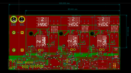
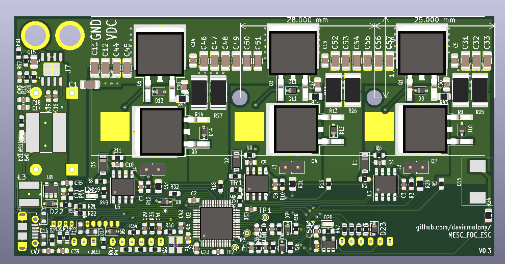
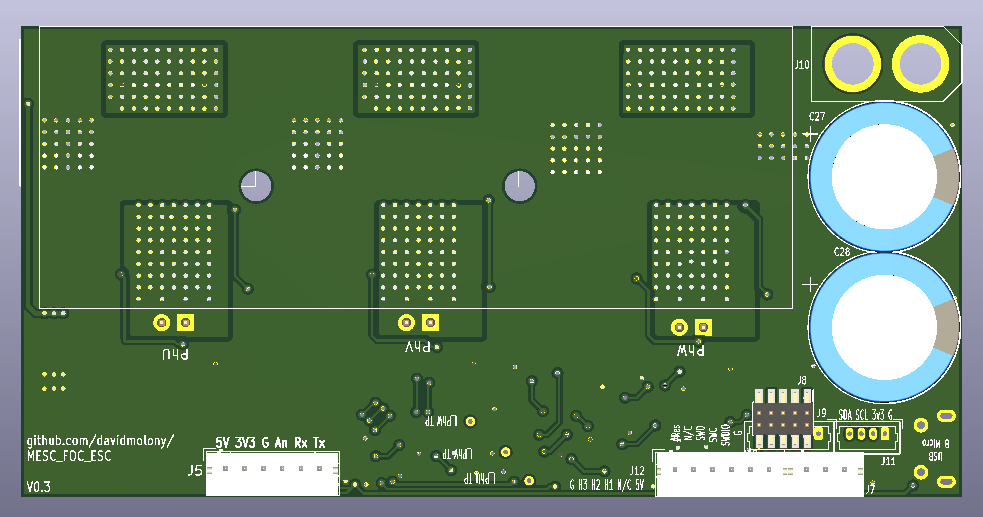
PCB updated, so Squeegee can fiddle with it provisionally. Not going to order for a while, but I think this will be all the connections it will ever have - it has ADC, UART, PWM, I2C/GPIO, CortexM, USB... seriously, I don't think it needs anything else. It's an ESC, not a do everything controller.

MESC_FOC_ESC_Top%20View.png

MESC_FOC_ESC_Bottom_View.png


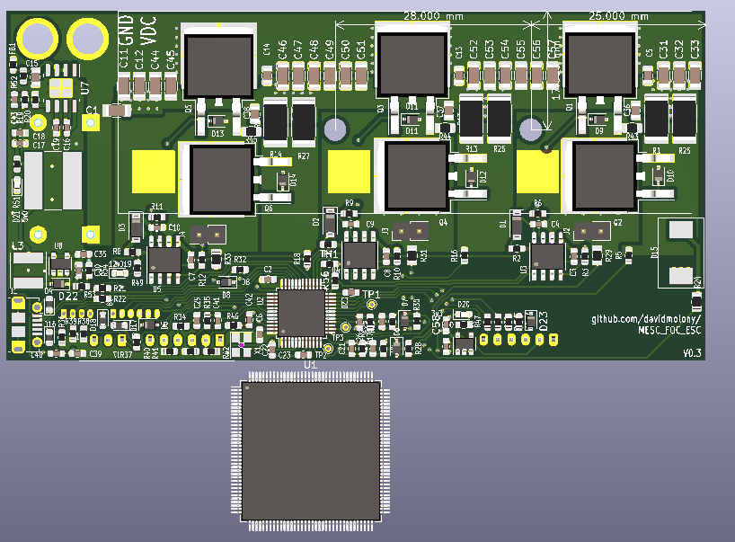
I also dropped the H7 144 pin into it just to see. It's enormous. One for later. Much later, needs opamps and stuff anyway. I have a nucleo H743, I'll see if I can compile and run the code on that one day.

MESC_FOC_ESC_Top%20View%20STM32H743ZI.png
 
mxlemming said:
PCB updated, so Squeegee can fiddle with it provisionally.

Ah, missed the update.
Had a quick look, I don't mind going through and "fixing" it. There are thing like these that are not good,Capture.PNGbut I'll spend the time only if you want me to... don't want to be a bother.

I hope your not going to stuff that 144 monster in there... as you said it's an esc. I'd be curious if it test fine on it though.
 
You proficient with GIT squeegee? I have a... poor working knowledge. If you want to check out the branch, fix it and check it back in, you can. If they are the only issues, might be easier if I do them. That said, it's often easier to spot problems on other people's stuff than your own, and I am not the tidiest person I know, so could be useful!

The 144pin version is not going in, for now. My long term goal is that the code is trivially portable, so at some point I'll make a board with that 144pin monster on it purely to test the portability. It may also be fairly easy to port the code to a 3 sensor VESChardware (I don't think I'll ever try to support 2 shunt, it's a pointless saving). Forking the hardware is certainly not my current priority.
 
mxlemming said:
You proficient with GIT squeegee? I have a... poor working knowledge.

I to have poor working knowledge of GIT... thankfully git desktop pull automatically.
I see I can create a fork, but not really interested in mucking up your project, so if I can just send you the PCB layout I'd prefer that. You can then publish it if it worth it.

I'll PM you.
 
mxlemming said:
I'm intrigued to know who though. Intrigued to know who you are also. I see UK on your profile. Cambridge per chance?

Yup, Cambridge, I'll get our mutual to poke you. He's been raving about H7s and though he might have got you.

Have you looked at the XT60PB or XT60PW or XT60PT for power input connectors? IF you think you'll do more than 60A cont then the XT90PB/XT90PW would be the next step up.
 
The mutual poked me. He has actually been helping with code formatting on this (my coding is... not very good) and did introduce me to STM about 6 years ago, but he can't take credit for pointing me to the H7 I'm afraid!

He tells me you made a pretty serious gokart.

I looked at the other XT60s, but they're less easily available than the standard, which you can buy in packs of 10 for a $ each from... everywhere. The caps next to them minimise the utility of the side exit. What was your thought?

XT90 I think is overkill, 60A at ~60V is ~3.6kW, which if continuous would launch my ebike to the moon. Surge capacity I imagine is higher, so short term getting 5kW through XT60 seems realistic, and given the visual look of the FET legs compared to the XT60, I know which I am betting on burning first ;).

It's kind of hard to know how much power you can actually get from these things given everything (FETs, VESCs, other ESCs...) are rated utterly unrealistically.
 
It's a pretty good go-kart, those hoverboard hub motors have outrageous torque. :lol:

The odd XT60s are a little trickier to find, but the with thru-hole types you can just fall back to wire. I've used the right angle thru-hole XT60s and XT30s on a couple of my projects and they've worked very well.

One guesstimate I've seen is to de-rate MOSFETs by 40-50%, so a 300A MOSFET will do 120-150A
 
Been really stuck for time this last few weeks, so progress lacking, but last night I got a few test results on the inductance and resistance measurements.

In lieu of a precision meter, I used my little Flipsky VESC 4.2 to get some data for 2 motors; both small RC aeroplane ones.. the Ebike motor is annoying to get onto my desk and has a different connector. Will try later. I know the VESC thinks it is 58uH.

Resistance%20measurement%2C%20MESC%20vs%20VESC.PNG


Inductance%20measurement%2C%20MESC%20vs%20VESC.PNG


The agreement is pretty good (resistance correlation is basically perfect), considering 1) the motors are both super low inductance, 2) I implemented the inductance and resistance from scratch and had no idea what numbers I should be getting (actually I only thought to get the VESC because I thought 1.7 ish uH was crazy low).


Kind of glad I didn't plough into the hall sensor alignment, thought of a much easier, better way of doing it last night.


Pinski, the current PCB can have a normal XT60 soldered straight to it - the through holes are the right pitch and diameter for this.

EDIT: Tabulated data
Voltage VESC VESC
Racerstar Racerstar
R L
14.7 0.04604 0.35
26.7 0.01475 1.19
34.7 0.0145 1.21
46.7 0.01434 1.22

Voltage VESC VESC
Propdrive Propdrive
R L
14.7 0.09545 3.43
26.7 0.052
34.7 0.0481 4.92
46.7 0.0448 5.01

Voltage MESC MESC
Racerstar Racerstar
R L
14.7 0.177 1.8
26.7 0.178 1.82
34.7 0.182 1.86
46.7 0.182 1.8

Voltage MESC MESC
Propdrive Propdrive
R L
14.7 0.0458 6.15
26.7 0.0468 6.29
34.7 0.047 6.309
46.7 0.049 6.33
 
mxlemming said:
XT90 I think is overkill, 60A at ~60V is ~3.6kW, which if continuous would launch my ebike to the moon. Surge capacity I imagine is higher, so short term getting 5kW through XT60 seems realistic, and given the visual look of the FET legs compared to the XT60, I know which I am betting on burning first ;).

It's kind of hard to know how much power you can actually get from these things given everything (FETs, VESCs, other ESCs...) are rated utterly unrealistically.

Here is some real data for you, measured it myself after the device held steady state for 10mins at the supplied current.

A TO-220 will have a leg temp of around 140C when the case temp is 75C. There was not much variation between the two devices I measured, one with 5.1mOhm, the other with 9.3mOhm RDSon. The amount of current to get to these values did vary significantly with the lower RDSon device handling 40% more current.
 
zombiess said:
Here is some real data for you, measured it myself after the device held study state for 10mins at the supplied current.

A TO-220 will have a leg temp of around 140C when the case them is 75C. There was not much variation between the two devices I measured, one with 5.1mOhm, the other with 9.3mOhm RDSon. The amount of current to get to these values did vary significantly with the lower RDSon device handling 40% more current.

What were your test conditions? what current into what FETs? TO-220 is basically the same as TO-263, just laid down on the PCB, so the comparison is probably good.

Is 80A continuous (say 10minutes), 100A for 10 seconds out of a TO-263 FET with an Rdson of ~3mohms realistic? That's what I'm hoping for. Top of FET will have a metal clamp, underside of PCB a decent size heatsink, and lots of Vias between the two sides. Kapton tape insulation for now.

If not, I shan't do anything for now (wait until I have the whole lot running first) but later I'll double up or dig out some PSOF/HSOF package fets.

It does seem painfully obvious to me that heatsinking is not avoidable by using bigger transistors. I^2 gets bigger very quickly, and switching losses actually increase with FET size so...
 
The devices I mentioned above were IRFB4115 and an IPP051N15N5, current was DC. The amount of current usable is of course thermally limited. IMO the amount doesn't matter as much as the differences between devices and the correlations in temperature found. I was able to gain enough data to make a usable model for CFD analysis. You'll have to forgive me for some of the vagueness as this is research I've worked on for my own product development, but I don't mind sharing basic info.

I put 80A DC on an IPP051N15N5 with no electrical insulator and thermal paste on a forced air cooled heat sink rated for 120W. Add in an electrical insulator and that device which was doing 80A now might only do 50A at the same steady state case/leg temp. Under the same test conditions the IRFB4115 did 57A (no insulator).

Here is a FLIR video I did which shows what the test setup was, but the DUT in this case is an IRFP4568.
https://youtu.be/qu6Q-RHhHXk

Good Silpad material should out perform the Kapton with heat sink grease as my low quality stuff was equal to the Kapton.

I don't think you'll get 80A AC for 10min with the SMD device, but please post up what you find out. I've seen TO-220 based setups with similar RDSon devices do 70-90A AC in testing. I have not tried to pass heat through vias to a heat sink, I'm curious to know how well it works. I have studied the difference in bare connection and addition of thermal paste, with thermal paste providing an additional ~25% current handling capacity.
 
That's an interesting video and set of data. By gross extrapolation, I conclude:
Your setup - 98A, 5mohm 150V FET, DC - 50W heat generated, limiting factor the leg, massive heatsinking

My setup - 80A, 3mohm 100V FET - 19.2W resistive loss, switching... some amount...say I assume a slow 100ns switch times, 80A80V 35kHz... = ~22W (upper limit)
Total ~40 W, less heatsinking, but share between 2 FETs (to an extent, 50% at half duty cycle).

It's definitely in a similar kind of region, less likely to have the leg as the hottest point like your setup did, since the leg and die bond is purely resistive so ~64% the power, but the lesser heatsinking isn't going to help. Overall, I think that your assessment of 80A continuous being optimistic sounds about right, but if you re-run at 70A70V => 14.7W resistive, 17W switching, 32W total (90W for the whole board, plus the other resistive losses) it starts to look more promising with decent airflow...

This is the first time I have run this calculation written down (done it in my head with the same result a few times), and it really does highlight the importance of the switching losses, they look like they account for as much as the resistive! It means more/bigger FETS != less heatsinking!

Considering 3 FETs - ST micro STH310N and the CR Micro CRSS042N10N (50p FET from some Chinese brand I took a flyer on when I got the last boards SMT'd) and Infineon IPT020N10N3ATMA1 - the most badass 100V H-SOF mosfet I can find:
STH310N Rdson 1.9mohm, rise time 108ns, fall time 40ns
CRSS042N10N Rdson 3.4mohm, rise time 32ns, fall time 27ns (do we believe these specs from a no name brand? Hell, do we believe ST micro or Infineon?)
IPT020N10N3ATMA1 1.7mohm, rise time 58ns, fall time 18ns

80A80V 35khz I get
STH310N 28.7W
CRSS042N10N 28.36W - less!!!
IPT020N10N3ATMA1 19.6W , assuming an unrealistic 1.7ohm gate drive (~7 amp gate drive required)

Well aha! I could use the TI CSD19536 which has rise and fall times of 8 and 6 ns respectively, a package limited continuous current of 200A (TO-263-3 :lol: ) and a 2.2mohm Rdson giving 15.64W, but very funny TI, how did you achieve your zero ohm gate drive? Measure the switch times at 10ohm and 5ohm and extrapolate to zero? How did you stop the tiny little leg fusing? Run it underwater? Why are you like this...

Quit bullshitting us TI, I have more reason to believe in CR micro than you.
 
Back
Top