New ground-up ESC - MESC_FOC_ESC

mxlemming said:
say I assume a slow 100ns switch times, 80A80V 35kHz... = ~22W (upper limit)

100ns is not slow, it's pretty fast for a high power device and could cause you some noise issues. Keep in mind you are talking about a 10MHz edge + any other fun stuff it excites. Best practice is to only switch as fast as needed.

Your switching loss estimate seems high, how are you estimating? They are going to be composed of the body diode reverse recovery + forward recovery + forward voltage drop (during dead time assuming synchronous rectification). Unless the device you are using specifies the switching energy it can be tricky to estimate without measuring it.

Personally I haven't seen a measurable power / thermal difference when using reasonable switching speed vs switching very fast in my own projects.

How do you plan to handle high currents on the PCB?
 
zombiess said:
100ns is not slow, it's pretty fast for a high power device and could cause you some noise issues. Keep in mind you are talking about a 10MHz edge + any other fun stuff it excites. Best practice is to only switch as fast as needed.

Your switching loss estimate seems high, how are you estimating? They are going to be composed of the body diode reverse recovery + forward recovery + forward voltage drop (during dead time assuming synchronous rectification). Unless the device you are using specifies the switching energy it can be tricky to estimate without measuring it.

Personally I haven't seen a measurable power / thermal difference when using reasonable switching speed vs switching very fast in my own projects.
100ns is slow compared top the times quoted with the gate resistors and results quoted in the data sheet. Which are roughly what I'm using. I think the switching time can be considered in multiple sections - which roughly correspond to the charge in the cap gate- slow at the start, there's a fast point where it actually switches, and the change to complete saturation. Most FETs are well saturated by 6V, but we drive them to 12 or so because of the exponential decay of voltage on the gate. Likewise, the same FETs barely switch before about 3V, and there's inductance on the PCB to overcome.

The energy absorbing region is in that 3-6V region where they're not saturated or off, and my calculation is just assuming it's a triangle of Vbus and time, current on the FET and switching frequency multiplied. It's a very crude estimate, but if you're passing those currents and that voltage, you will dissipate that much power in that switching time. It's just a matter of how you're defining switching time.

zombiess said:
How do you plan to handle high currents on the PCB?
When I calculated the resistance of the PCB (used some online calculator and estimated the widths, given the return path) I got less than 0.5mohm on ground and less than 1mohm on Vbus. With 80 amps that's roughly 6 watts, which can just go down the heatsink, it's 10% at most of the total power dissipation.

If it turns out to be an issue, the easiest way is to just put extra wire connection pads for ground and Vbus near the FETs like the bigger VESCs.
 
Hold that thought, I might have misunderestimated the PCB resistance... Which might explain an annoying offset in current readings between channels... Going to add some thick wires between the shunt grounds...

Edit 15 mins later:

I have tried 4 online PCB trace calculators and for similar inputs they come back with different results... By a lot. Looks like the resistance is more like 2-3mohms which is a problem for the current sensing with 1mohm shunts :s. Easily solved with some 12 guage wire... For the prototypes... But this does represent a problem for any serial production.

Well that was a clanger.
 
mxlemming said:
100ns is slow compared top the times quoted with the gate resistors and results quoted in the data sheet. Which are roughly what I'm using.

Physics is the ultimate rule maker, so one way or the other you'll get answers. I'm going off of personal experience + sage advice from some advanced power electronics EE's. Some parts don't mind switching fast, others hate it, all of them depend heavily on a good layout. Datasheets on these parts != real world application.

I'm quite interested to see how your thermal performance works out, it could open up some design options.

Learning physics / electronics has taught me that math is extremely precise, but can it be wildly inaccurate. Works in theory, works on paper, works in simulation, fails real world... grrr.
 
I'm intrigued as well, I'm aware I'm diverting from the beaten track. I just fitted 12awg wire between the shunts, so that in the off phase, when sampling current, any error caused by PCB resistance should be greatly decreased.

It seems to have made sod all difference, the motor spins with the same subjective torque and similar looking current traces, implying the PCB resistance is fairly small compared to the shunts.

I'm becoming less and less impressed with the opamps built into this MCU. The offsets I'm seeing are kind of huge; at zero current (FETs disabled) I'm seeing 1759, 1860 and 1890 ADC counts on a nominal 16x gain and pull up to 100mV. It should be closer to 2000 (0.1*16*4096/3.3=1985?), and all channels should be the same. The issue i can see with my multimeter is the opamp not the adc. The point of using this chip was for hardware over current protection, but it's seeming like the opamp might just be a bit too crappy. Behavior is similar on all my boards, not just one broken one of them. Moving to some 15 cent ina181 opamps would be a nice thought but I'd lose the hardware over current protection. Or would I...
 
EDIT: Ignore the pics below that probably don;t load, this is for the old version of the board, which while good enough for some things, well it's not really relevant any more and google photos does not host nicely. The pics further down with the newer board show exactly the same thing, but better and for the new hardware.

Needed some wins after last night's disappointment.
e7rM7-fyuGPFjO6gDsMGFzLRtP76G08anw41sN79KJKL4pQ7vjPBskVZTJqBvtgZJb9BY-8-4j1hSD0kNnv8Cx3EQ6Worpo_mqeZcC1pljCml4pmDoCSXYb5DGjoIP6hcQR_slG7iyKy_cYrN_j0b3bTugzYzZixu3AgNpFzDAFCn3AXK0iFAvKPqJ9lTIT4IKDIs9rNj5tX5Ytk8wOVRVPrV8z4fumSb-hVlTssjUGNKPlWvGEePqNceijx4XNjayYnNGuDhEO_8DWBXZlnjMixutQqoYyHKdkGh9ac2OSERazwcr0JURAJhnt6CNVHJxCh81xtnKtQLv-5civPCl8rU69ErpX9_r6iihu1UgxdgK_o-dehmWmHTuwZ4fQ1xZbaLqCGJOO2q0EEIvgvlb97Jcmbf436EVRnF7y9GTn1bgqLhkKG7F2ej69yX_cGVw319cExGBM1wQs2Y175O9AbeSVxZLR_5aK3vO9PI6MAy45B9TnjWK7cJDfDMdjvIBQ5My3X8dQqLI7p8Zv-U7NJs75sfNAEtw0FG6d4b2d_-I0SC9XKvk_zvZr9Fo7-CrsAvTv0tIvYbFS6v4XKMGqzXEC5jU2w7z9WE0WIYMEID88QNBTvvaKSLEZyTTH0ymDAMp83wHXYBPLOPXaN1885RwEU7RO0DGifY8wzozi4RQE=w811-h608-no

UrQidjiQqFJ7CGDF456LXREYb7z1DvtUbnhqpZPNMZGBxuHrmCVvUByQVh0IaHFHAsf-3CEyfaC7RFb7Bq_B1ULebZsExE781RwPMovmhJ67NmZP0Ou-mP3nLXEFVZwK_dtbHyJI6zxwfJWT4hjxbTDsT9EPPy7iEhHnSWxO4G6K1EHIGU81yg7g9mr5qm9Z1mbZvxKFJf8XEd45kQMDm0MKvfhVfCzxu1n9FVVqFLbR57FdLNBdYTUs5WeUU9HCE8crZHXJyc69-JxQLKBj13mcpHPC8FclTst7hDdpm8lDFpAznZgDFKM3sBsJf1COXymwWdVTJCu2gITiddC7yFyYWy3GcphNprEvF_WFHyFMmvTh_zPuk9dulJqWyGp3-Ewzz3L2E3f5BlsVac3eVKFo1cY_wvMKnlAJuSRjGqql883aK93KuD-V5UAr70UunxdDdjPUpy3LDHv15qng9rdqKh-rC8156oforCUBPo3lHxhpEk3lGa-s3TnSRf8S__xtZbTISsNpwJKLjiHDhm4fWbLT07SMztIQ6_IHjHyoygBgSU3-7SdFnpEme43iRzxwQplscr1DzzJ8Oyf4y6GTfpRziE3GZnjuN2jDujUDSGEz6jExCwPV76lKNUO3QVjVAh7Dp5Fxwlhk_aMtKiZ8p6PhjcLj8OlAqvaJrLIpINw=w811-h608-no


It appears that the ringing is only ~2.5V?!?!? Am I getting something wrong? This seems improbably low. It seems to not change much with load, a bit, more in shape than magnitude. I am only really able to get the phase currents up to about 20A, beyond that I struggle to load the little desktop motor.

Using the ground clip instead of the spring gives about 7V.
WIWT8AaJuVBp-Uu8Ve_rvu9PvSm6DpUqsGf3BdttDiW5m2uMSxslUJIzQMj37kUI1rSfGaNpWgbOuKpnO1WitlwtPRFR03JiLWqoed0q6nYuJNisj8Ux-f1_WIN0U7Er6Z2c24Xwl_2l4e7h2mY6WP0gPdPlsW1pLILN7qqjJtM3Ug71fwgRmIcDPsBgG1oi3rSSNZrQTMY2GG3NCrs3ymDYUTnSAaY8Xv4u3tCsxKmBemIaRkxFLmU4_uCVeOzPbAHKJ7bBhG34wlk5Zwq0-lozjlPAJk0Nn5ctEUB8Iwe3Y2uo8G80ly_jZh-drGNNt7pFBPpV9JYwr9BJGU5B2LaxYcy6CGYfB_OzUqjlLcv2T9vihmLyxngJ8JvZwaLMxxGDRzYX8vMX-UfCe6loCDBj61PTm7B3vnAS9Uic83x_E7ldxIVmqbSCzSAlzxtAReNAG6mGHh7SaMMr1-oMMr-018yaEc-Tb2Mw-f2oBHlyQ6-5uBGr7lwGAD3pSqS2g4gqZKYgJOs4TBHv5_O_YIbqCjmv2YshtRVNE1bl-Xd__sPH_Ap5gvqhZz8fMkJc3btv4gNU7EvcDz-BC0pIaYxoF3xtC7wJ9QFpL52rwO14EwTqGFbsy3s0HQR7E0QQhLYu-is-hxsft149sPSFzouKPDOYtdSfoGTNnE1gnuqihyE=w811-h608-no

Can also see the switching times here - bloody fast. Looking like about 30ns. Yet nothing bad seems to happen as a result...

I set the dead time originally to 415ns. After looking at these traces, I set it to 135ns (could see the asynchronous body diode rectification taking about 400ns before the rise started), nothing bad happened. Current consumption has not gone up.

Also re-wrote the Clark transform to minimise the use of the noisy ADC (the one the DCDC converter is messing with) and to not use the ADC on the highest voltage phase. It's much quieter in operation now, and the FOC Id&Iq currents I see through the debugger are much much better controlled. Step change in performance.

Could anyone comment on the seemingly implausibly low ringing? I know I tried to design it with tight, low inductance switching loops, but this is way way beyond anything I had ever expected, and the switching speeds are just nuts, yet work fine as far as I can see...
 
That's not unusual if you get low loop area. I've done 100's of amps in 70-100ns with similar results, but I always slow it down to improve reliability. Fast edges will often lead to noise coupling into other stuff. I do a lot of paralleling of devices, and fast switching has shown worse current sharing between devices, not applicable in your case right now.

In some high power applications they can cause issues like premature failure of bearings in a motor because of capacitive coupling effects. Not applicable to your application, just sharing some additional info.
https://www.motioncontroltips.com/what-are-bearing-currents-and-what-causes-them/

Calculate your layout inductance, it will probably be 15-25nH.
 
V0.4%20board%20bottom.jpg


V0.4%20board%20top.jpg


Massive board rearrangement since Zombies noticing that the board resistance is probably an issue. Board is now a different shape - 84*66.5mm(5586mm2), instead of 100*50. This is a ~12% area increase which is annoying but oh well. Should allow for a big old lump of copper on the top to pass the ground current between shunts and ground pin, and hopefully better analogue readings as a result. VDC subject to less current, and have observed the current PCB doesn't get too hot riding Ebike around with ~60 phase amps, so that is on the bottom, with no intention of needing any reinforcement.

Added INA181, because, quite simply it appears that the onboard opamps of the F303 are not fit for purpose. After wondering for ages why current readings are randomly offset from each other at zero current, soldering huge jumper wires to the boards, observing the current being different on each of 3 phases post opamp, I have concluded that external 13 cent opamps are a worthwhile investment, and will aid portability to the F4/H7/L4/XMC4100/whatever. Should maintain compatibility with internal opamps as well as external ones.

I've also been playing around with the Infineon XMC FOC libraries, and am rather impressed. Seriously easy to set up, and the sensorless control is really good. I made a board with little TO-252 FETs a year ago, and frankly the layout was crap, but it just works beautifully. The downside compared to STM is that it's a more involved ecosystem to get into, and the peripherals are way harder to get your head around, but they actually seem to be better, more flexible. The other downside is no onboard hardware overcurrent/voltage protection, and it is not effectively implemented in software, so I have burnt a few FETs, whereas the ST libraries and my control algorithm seem broadly utterly immune. Probably easy enough to implement as a few lines in the ADC interrupt, but that's for another day.

On the MESC firmware side, I've been riding the Ebike around with it, and it is definitely not as good as the VESC yet, but not a million miles off. Main difference is noise, and slightly slower (probably due to lack of over modulation ability).

Wish I had more time and energy to spend on this. Still only getting 5 or 6 hours a week :(
 
Apologies to Qwerkus and Stancecoke for not sending boards to them, I just haven't been quite happy enough with the results, basically because of the opamp situation. It's a shame, because it's been so good otherwise.
 
Just did 9km through the park, only superficially pedalling, weaving around small paths, lots of speed up slow down... probably peaking at 25-28km/h, and going basically as fast as I could given the weaviness of the route In that distance my 3p12s pack of Samsung 30Q cells went from 48.7V (4.058V/cell)to 45.9V (3.825V/cell), which cross referencing with
https://lygte-info.dk/review/batteries2012/Samsung%20INR18650-30Q%203000mAh%20%28Pink%29%20UK.html
leads me to believe I used about 0.875Ah*3cells at about 47V = 123Wh. 13.7Wh/km, 21.9Wh/mile.

Is this good for zero pedalling? I have absolutely no idea what is realistic, and the net is awash with "Oh, I get about 9 if I pedal hard" and "My 12kW looneybike gets about 90Wh/km..."

This is the setup, complete with glorious levels of tape.
cLRoR9OlKMVrNVpRT_nouo6O2lhoHmdvIFZbrUI3ISQlp_NaampdRDRrAbxeB4Aw1nR8EAkSIFOeri7wbIBUSck_9Bth_qVwoREdOlrdGXcwFlYkAaz85ECvEtibjUplDdli276NgBEO005oXX5ciM216lJyawHK2ogytyXyLAgS4g86qIU848moWLfRfWO0jRP--OLcxLc8tIFkdlD8U1MuLY1VVhLqa1_BCFmZ0TJBSX6N4jpd2LUQ9MrrJlm3hzFqBYbdQk0j-hhQR3CoRH6UdP38LbvDplQFpP-Cge-SfzIZHtxUlh1DEIB9HabY7yEa3MxMQF8d_3-fTGqxVp8hRik-DUIKaFvP4_mzKDbeU-S5QCq5CEedfAnwQyqe5KbwKgxGK_dKHzAsIgH8SE3oUvbgm_l4H2MFmP3fJ5mh4GfW9Ik8nNS5ysta_ddFw1HQE87A7YXEnkHLiQvfXJ6bPbvzbBIxAiU04cBrXFhPsi4WNu8zF_Uht8OM8_8PWkAw9q_yFBLdAiSnXUme-_huZzpO1A6g3qvnhAoREJ7cEZ1JOX_axQMN3IcXkIiIbe1Blk7zyBxl9H1f1YmMf-vXU0NVGdXL_2xRPPgLqk-3BXWBAtdecbDbzDB5-VffluyPnYodIWy6MkqPrLFVA-PuUSFN7athwD4oa0-H6GbaLwI=w887-h665-no


Nothing got even slightly hot. Controller was cold, battery cold, motor... noticably warmer than ambient, but basically cold...
 
Good news! The consumption is in a normal range for the speed without pedaling.

Sadly we can't see your photo...

The Lishui hardware uses a quad OP Amp TSV914. Three channels are used to amplify the shunt voltages and the fourth channel is used for hardware protection, it switches the Timer 1 break pin (PB12 for the STM32F103) at overcurrent.
With not using the internal opamps you will have enough I/O pins left for all purposes :D

regards
stancecoke
 
MESC%20on%20Ebike.jpg


Maybe hosting on Github rather than Google photos helps?

I find google photos inexplicable... It works on half my browsers/unrelated work laptop/... but not on my phone/...
 
mxlemming said:
probably peaking at 25-28km/h

I saw your commit for the bottom clamping. I understand, what you are doing, but I never heard of that procedure and I have no idea, why this should lead to higher speeds :? . Can you explain the idea of bottom clamping, please?!

In your look up table I see a normal sinusoidal waveform. Are you not using space vector modulation?

regards
stancecoke
 
There are a few options for modulation
1) inverse park and Clark gives sinusoidal pwm
2) svpwm gives mid clamped pwm with 15%higher modulation before 0 or 100&pwm
3) top/bottom clamp maps the sinusoidal output lowest phase to zero, which reduces the switching losses slightly and gets the same Max modulation as with svpwm, but more harmonics. Fewer clock cycles to implement and longer periods in the shunt conduction so generally better ADC reads... The other big win with this scheme is safe saturation - svpwm sinusoidal etc all result in carnage if you go below zero on a phase... It'll invert with most timer set up.

I'm trying to implement a third harmonic injection routine. Tbc
 
mxlemming said:
2) svpwm gives mid clamped pwm with 15%higher modulation before 0 or 100&pwm
....
I'm trying to implement a third harmonic injection routine. Tbc

Hm, for me, space vector modulation and third harmonic injection was always the same.... :)

https://www.switchcraft.org/learning/2017/3/15/space-vector-pwm-intro

image-asset.gif


I've implemented the routine, described in the STM paper, chapter 4.11. With this, you don't need the inverse clarke, you can calculate the three phase duty cycles directly from Ualpha and Ubeta...

regards
stancecoke
 
Third harmonic and space vector are definitely different, though they reach the same eventual goal.

I'm kind of intrigued to try the alternatives. Everyone uses svpwm. The st version in that paper while starting from alpha beta, still seems to have a lot of clock cycle usage (not an obvious improvement over the inverse Clarke anyway), and actually iirc is available from their library... I think there will always be quite some computation. Happy to try porting a version of your implementation. Bottom clamp is noticeably noisier and needs improving.
 
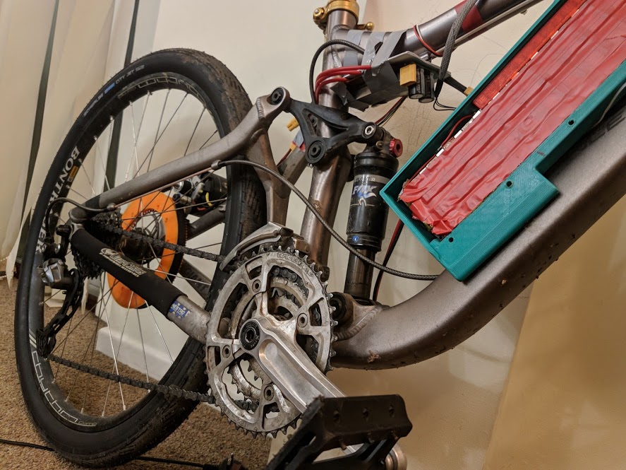
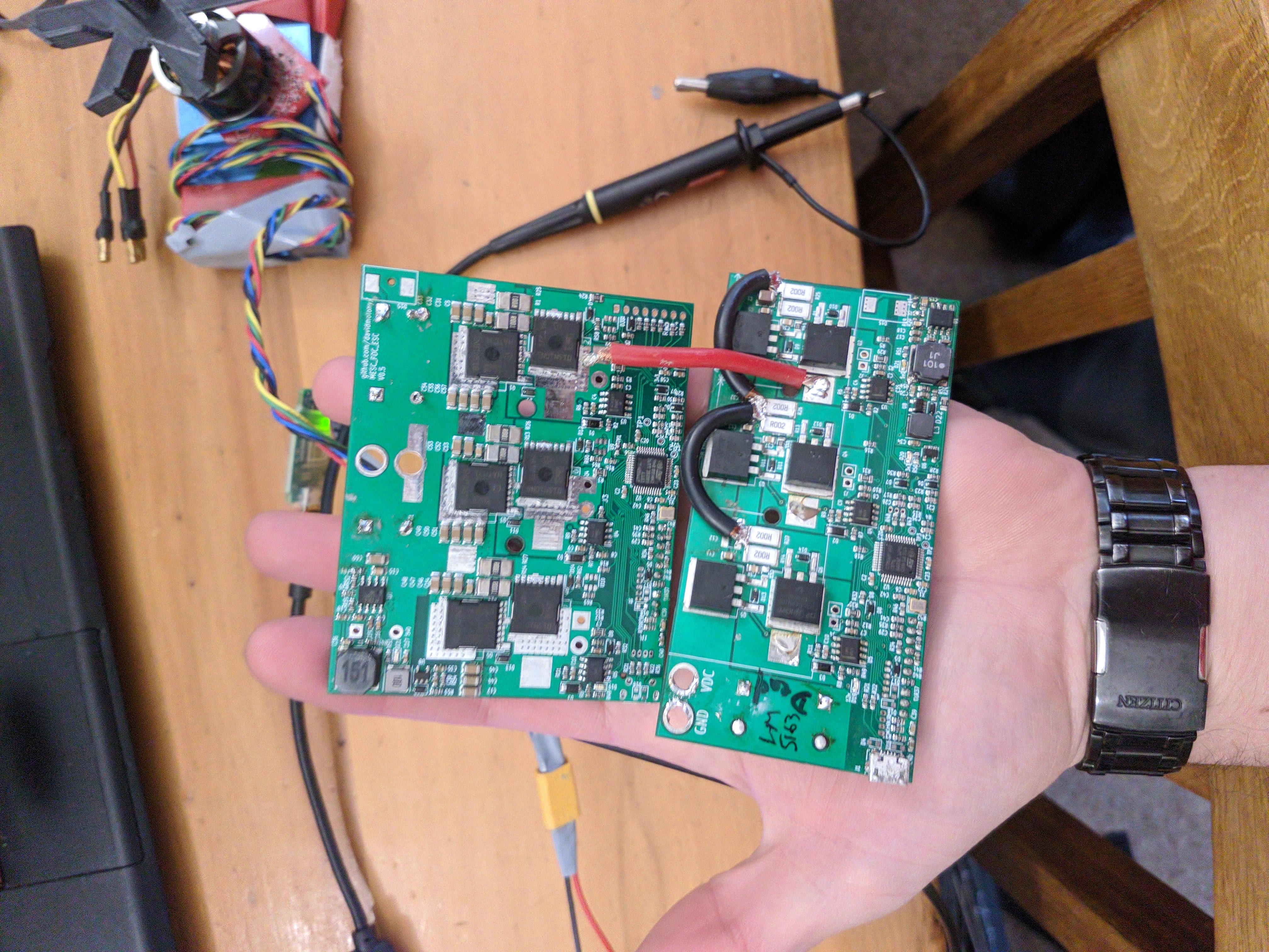
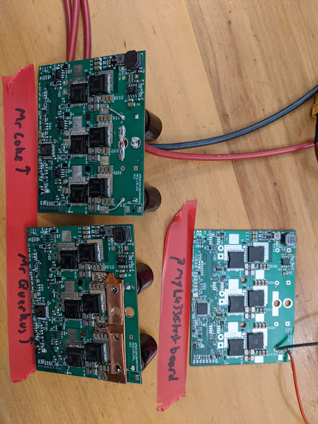
New boards finally arrived last Friday, after FedEx took care of them for me, for 3 weeks. Thanks FedEx!

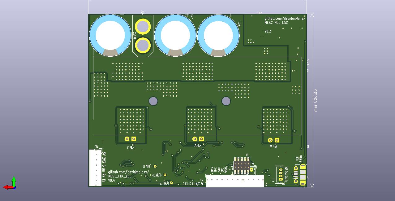
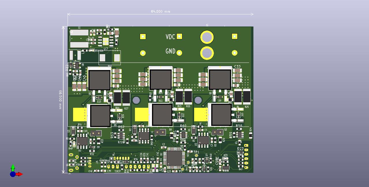
They are slightly larger - about 10% more area, but narrowed and deeper than the old ones. Still not exactly huge.

IMG_20210109_151837.jpg


There have been some highs and lows! but the new boards seem really nice. I really really do not have enough time to be doing this unfortunately. I'd love to be spending hours a week, but alas.

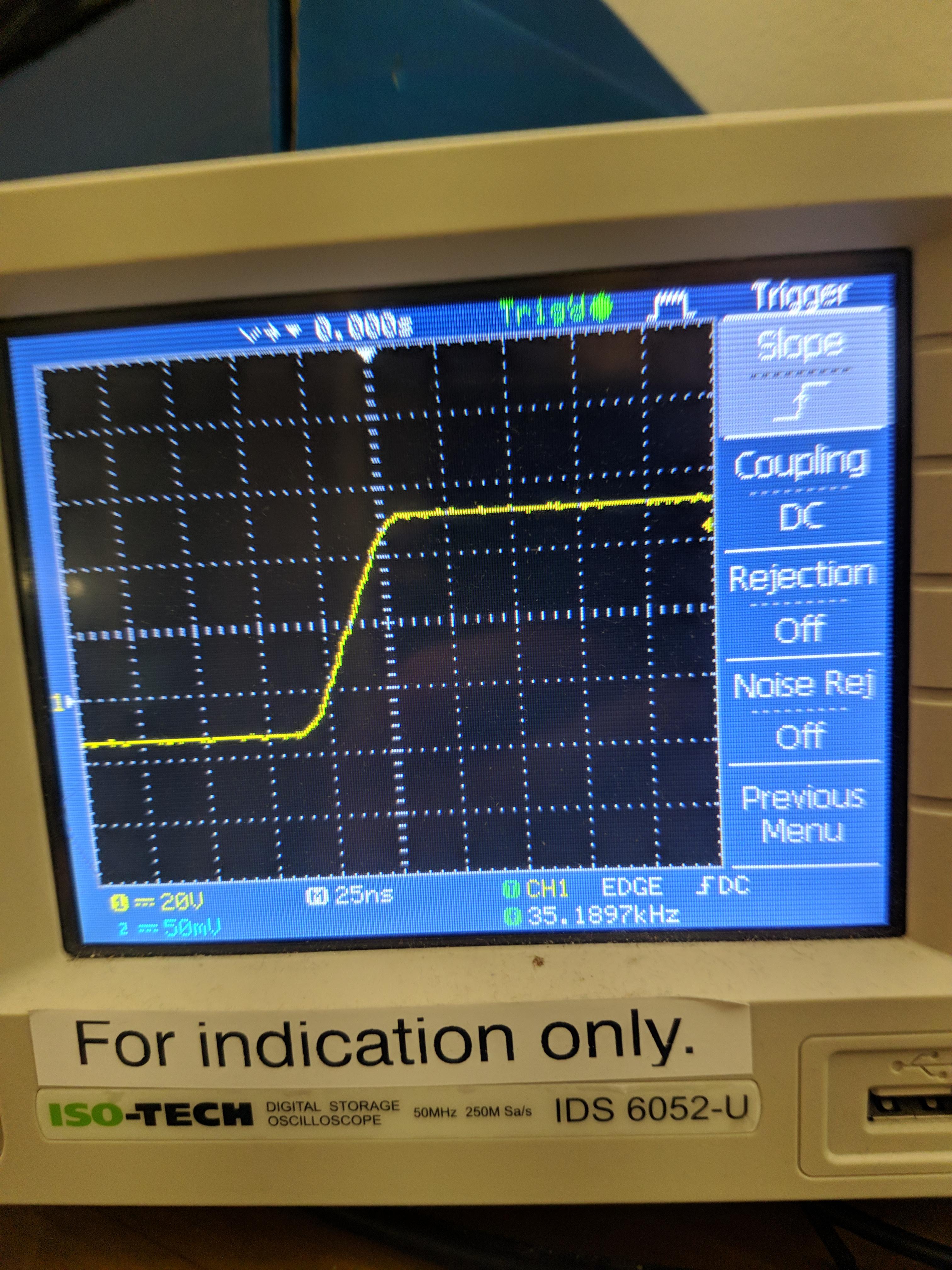
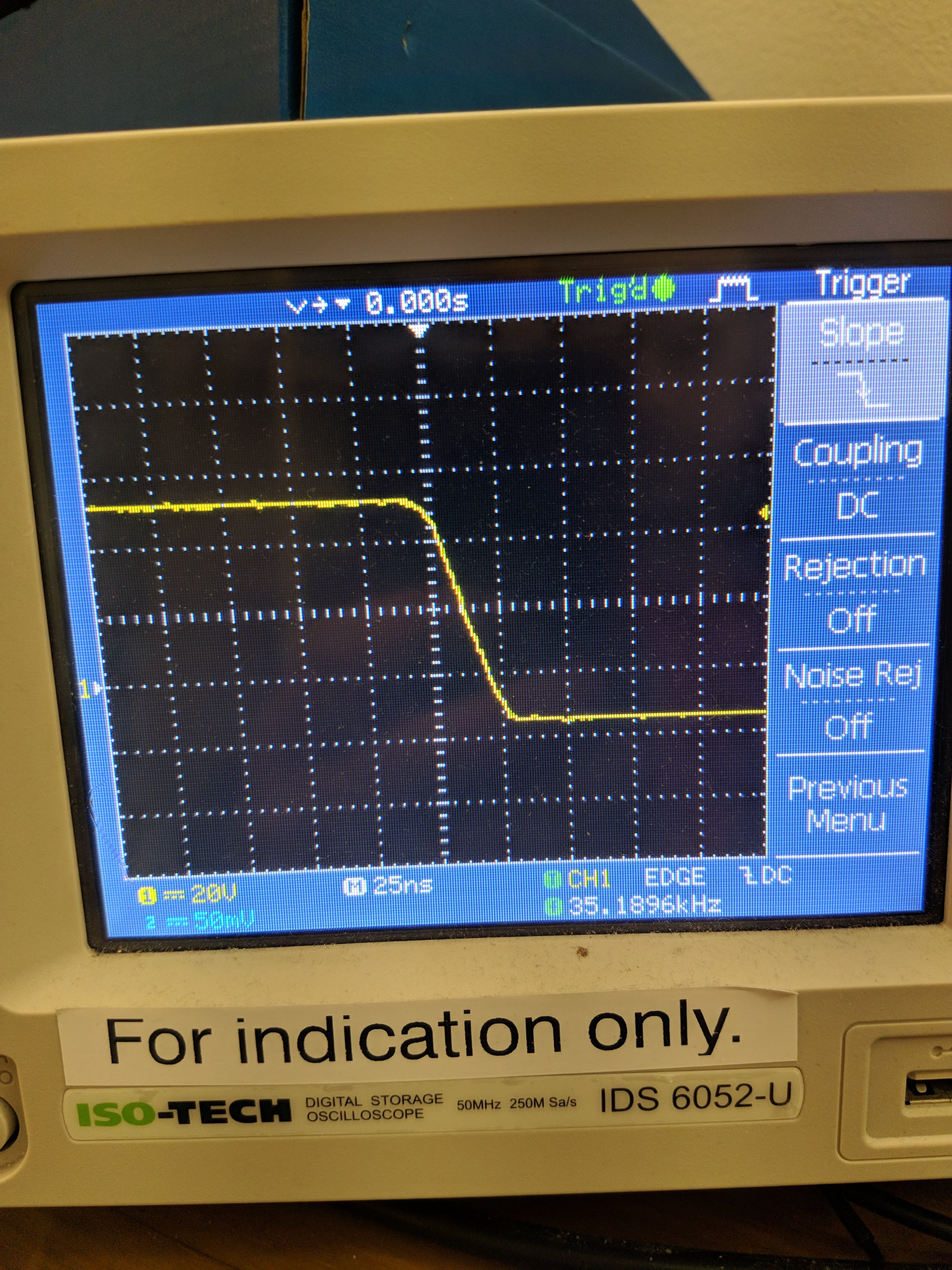
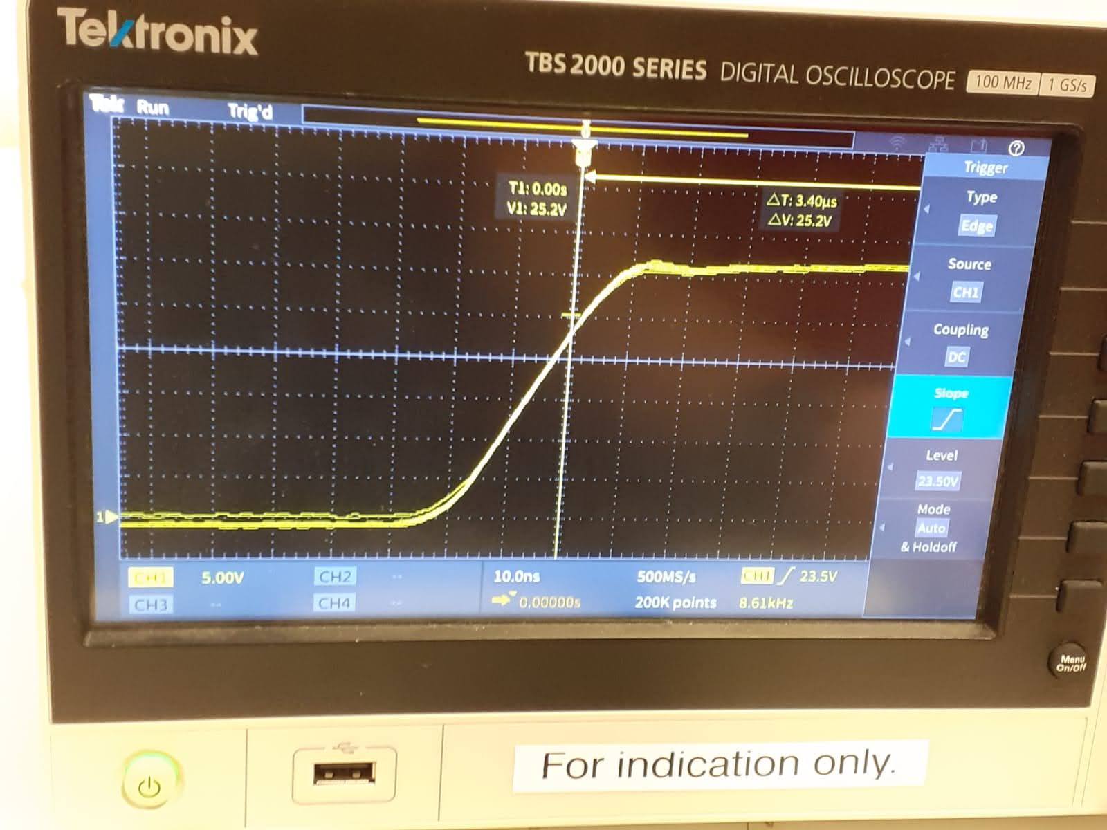
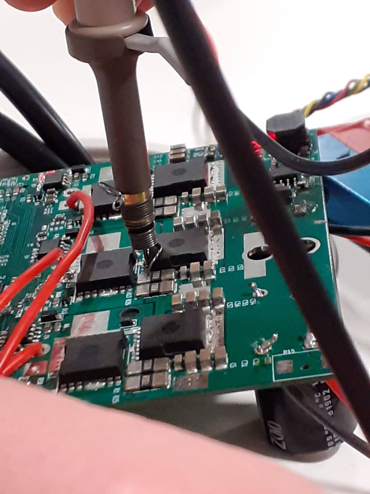
The ringing, or lack of it is beautiful. I find this incredible, bordering on impossible - roughly 30ns switching time and zero ringing. Mind blown; I designed the layout to be very very low inductance, but this exceeds all expectations... I thought the old one was good. The new FETs and layoutith the extra ground plane (4 layer is now same price as 2 layer so I thought meh, why not) seems to have worked a treat... Let's hope it works well when it finally stops raining and I can take it out to play. I have been warned many times by Zombies and an old colleague that switching this fast might be a bad idea, but efficiency! I am hoping that with this little ringing, nothing bad is going to happen.
IMG_20210109_201614.jpg

IMG_20210109_201707.jpg

It was so good, I thought... This can't possibly be real, so I took it to work to use the expensive 'scope... and it seems it really is basically ringing free. So this should be good up to 20s 84V with the 100V FETs and 600V gate drives!
IMG-20210111-WA0015.jpg


IMG-20210111-WA0011.jpg


Additionally, the current waveforms are a lot nicer since the DCDC converters have been moved away from the shunt lines, even before I have tried the standalone Opamps - they might not be needed after all. Much much quieter. I am generally very pleased so far with this new revision.

The bad news is that I am nearly unable to solder the wires to the board, the heat sinking into the various copper pours is a complete nightmare to solder to.

And of course... when drinking too much, and when it is pouring with rain so you can't really go outside, there's always repurposing the old PCB to be done. :lol: Just wired my headphone output into the analog of the STM32 and it modulates the PWM with the music, so the motor plays music... and if I attach a speaker to it, it plays music loud. :D
[youtube]https://www.youtube.com/watch?v=OGw6MtW5sXE&feature=youtu.be[/youtube]

Edit: Moved the pictures from google photos to Github, because Google is still inexplicable... It works on half my devices with random browsers.
 
Really clean signals, but at how much current? Normally there is some turn-off overshoot, where the area under the overshoot is L*I, that is the flux in the output loop (FETs+caps), and both factors are non-zero. L*I is the same as the integral of Udt, where U is the voltage above the supply voltage.
Can you add the pictures also here: https://endless-sphere.com/forums/viewtopic.php?f=30&t=107672&start=75#p1596105
Maybe you can see your google photos when you are logged in but noone else can see them? :)
 
peters said:
Really clean signals, but at how much current? Normally there is some turn-off overshoot, where the area under the overshoot is L*I, that is the flux in the output loop (FETs+caps), and both factors are non-zero. L*I is the same as the integral of Udt, where U is the voltage above the supply voltage.
Can you add the pictures also here: https://endless-sphere.com/forums/viewtopic.php?f=30&t=107672&start=75#p1596105
Maybe you can see your google photos when you are logged in but noone else can see them? :)

Current is only about 4A on my desk with the small motor. It's quite hard for me to get high currents at my desk with an EBike motor, they generate a load of torque, and when spinning have enough energy to grind holes in my desk. I will get more scope traces later, I think it's probably OK to just load a lot of Id rather than Iq, which is a lot easier to handle obviously.

Previous experiments up to ~20A (beyond that I cannot stop the motor if anything goes wrong) had very little change in ringing.

I'm not going to bother fixing those old pics, they show exactly the same thing, but with the old version of the board - some ringing, roughly 2.5V magnitude. In future, I will only host on Github. The issue isn't login... I can;t work out what it is, but I can see it on my wife's computer but not phone. Google has some strange yet inconsistent way of stopping hosting pics I think.
 
Finally got it on the EBike, wired up... Was really really easy to set up since I updated the Hall detection.

Took it out, and the previous over current problems seem to have gone now that it can read up to 200A... it didn't trip at least.

Was pretty fast. Set it up to control Id to 80 amps max, depending on throttle in, and... Took it for a spin up and down the road and up the hill next to my house.

Unfortunately, while the ESC barely got hot... warm even, and the motor was only warmish, the BMS decided it needed to limit the current and did so by catching fire at about 30km/h up the hill.

Burnt%20BMS%20FET.jpg


I guess I would call this a success. Even though my EBike is no longer functional. ESC didn't give a shit, it carried on until I let go of the throttle.

Buy cheap buy twice I guess. At least the weather is so bad here I don't really want to go out anyway.

Apologies to Stancecoke and Qwerkus for not sending them one yet, they are nearly ready, I have just been insanely busy with work work the last week, and missing of all things the programming headers and 8 way JST PHs :roll: , which I thought I had a tape of but seem to have lost. As usual, this is the fun part of my life, but not the bit that puts bread on the table.
V0.5%20ESCs%20nearly%20prepped.jpg

Here they are, once those pesky headers arrive, I'll post them.
 
Don't you want to try double pulse tests with an air core inductor (wire wound on a plastic tube or similar) instead of the motor? The waveforms at 80A, 100A or even higher would show more about the performance of the board.
I checked out the layout, the In1 layer seems to be an effective eddy current shielding for the output loop that probably helps to achieve the low inductance.
 
I would like to... What do you anticipate being different to running 35000 pulses a second and making it push 80amps?
 
It would be interesting to see the higher limits of the circuit in voltage and current. At the highest current the turn-off overshoot on Vds would define the max applicable battery voltage, but also at turn-on the reverse recovery transient of the non-switching FET (internal diode) can generate a short but high spike on Vds, and also oscillation, if there's any. There are also the Vgs transients on both the switching and non-switching FETs to check, the negative spike on the non-switching FET Vgs that sometimes can kill the gate driver chip (unlikely in this case), and the possible noise the power circuit induces in the low voltage supplies and the current sensors. So the signal integrity in general.
Then the thermal performance is also interesting: for how long it could sustain the highest current without overheating, but that would require a high power load.
 
Just a few quick videos about setting up a motor.
https://youtu.be/ML-UTY0gww4
https://youtu.be/K1Jfvm3iwu8

Unfortunately, this project is going to have to slow down even more over the next few months, since I am about to start a new contract, which will take up a lot more of my time and require me to be more alert than my current corporate drone job. It's not going to die out, but it might be a while before the firmware becomes useful for mass use. Unless Mr Coke manages to port his EBics firmware to it, in which case it may constitute a decent lump of hardware to run an ebike on.

Putting it in the post tomorrow :lol:
 
mxlemming said:
peters said:
Really clean signals, but at how much current?

Current is only about 4A on my desk with the small motor. It's quite hard for me to get high currents at my desk with an EBike motor, they generate a load of torque, and when spinning have enough energy to grind holes in my desk.
A switching trace at 4A is worthless, you want to find how bad your voltage overshoot is, and V=L*di/dt. If your "i" is like 2% of your worst case scenario, then your measured overshoot is likely in the 2% range of what you will really have down the road.

That's why so much effort is spent getting the test rig right, a double pulse test doesn't need a high power supply, in fact you typically just charge the DC link and disconnect the power supply right before the test, especially when you want to make sure the short circuit protections can trip with the energy of the DC Link alone.
 
Back
Top