Open source BMS for 48V to 400V lithium-ion battery pack

I have an un-related question regards DECO-275A controller. I saw your comments on it in one of your response in other post.

My question is once you have the program installed on your PC, how do you connect with the controller? is it via blue tooth/wireless connection or you need to have a wired connector to connect?

Thanks for answer my question.
 
@danli_new : ask this on the deco controller section instead.

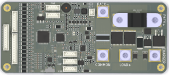
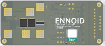
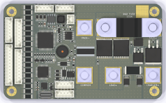
After many hours spent working on the third iteration, I came up to the conclusion that low side current sensing is the only way to go at the moment, so I had no choice, but to make some changes to the initial PCB layout, still the same 140x60mm:

18s discharge BMS.png
18s discharge BMS-backside.png

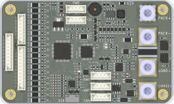
There is also a smaller (100x60mm) and less expensive charge only version that will be tested very soon:
Charge only 18S.png
 
Looks like a great BMS job.

I plan to build a 3p5s14s8p pack (15 modules each 14s8p) to supply 300V (5s * 14s) and 30 kWh, using 21700 cells (Samsung 50E). I am looking for a suitable BMS. I wonder if your BMS is what I need? The 5Ah cell is rated 2C cont. and a peak of 3C. That would be 8*5*2 = 80A cont. per module and 120A peak. Also need bus interface (CAN bus), and access to all parameters. Your BMS is designed for 18s. Would it take 14s? Can the BMS run off the pack power or needs its own supply? Can it also charge, or does it need a CCCV charger?

Would a 3p4s18s8p architecture be superior? Or would you recommend 4s3p18s8p?

Thanks!
 
You must go with the Master-HV board with master/slave board topology & mechanical contactors at such high voltage level. The 18S solidstate version shown can only handle 18 cells in series maximum. The future 24S version will be able to handle 24 cells in series max. One option in your case would be to lower the total system voltage & increase the current for having the same power output. Going lower in voltage reduces the overall system cost by a lot, but it all depends of your project details that I am not aware of.
 
The application is for electric flight where weight and efficiency are critical. Efficient lightweight PMSM motors are HV and can be up to 600V.

I assume your BMS can accept 14s and not just 18s?

If there is one BMS for every 14s module, what stops you from putting modules in series to achieve higher voltages? Note that all charging will be done at 60V (14s) so each module gets its own isolated charger, or alternately the power supply can rotate through the modules. Note that I assume the bus connection is optoisolated.

If you had 15 modules (each 14s8p and with its own BMS), would you string them 5s3p or 3p5s?

Also why would each module have its own contactor? Does not the power mosfet on the BMS act as a contactor?

My apologies for asking very basic questions. I have some way to go to understand the BMS.
 
If there is one BMS for every 14s module, what stops you from putting modules in series to achieve higher voltages?

You could use the charge only BMS-SS version (A charge only BMS-SS has no ability to turn off the discharge current path). The full BMS-SS version (with charge & discharge cutoffs) is not possible in your case.

A full solidstate BMS array can only be possible if each unit has FET rated for the total string voltage and designed to operate at such high voltage which is not the case with the actual full BMS 18S design. This would make each unit heavier, bigger and way more expensive. I don't think it would make sense to go that way.

Yes each unit can monitor from 5S minimum and up to 18S.
you need a CCCV charger.
 
Thanks ENNOID. I just visited your website and was not aware that you were doing other stuff too. It is a very nice website and more success to you.

I am thinking of an Emrax 208 motor. When would your motor be available? As for your inverter, would it work with the Emrax?

I will take a closer look at the BMS and your battery pack. I like your battery pack very much. Seems to be quite lightweight and small using hex packing. I would move to 21700 cells (Samsung 50E). The hex battery grid should be just at the top and bottom of the cells so the cells can cool better and be lighter (not clear from the pix, but it seems cells are enclosed in plastic). My modules will be of two banks, each 14s8p, equivalent to 14s12p 18650, with the 21700 cells on 22.5 mm centers. The banks in a module can be tied serially or in parallel or be isolated, giving me 28s8p or 14s16p or 2x14s8p, about 4 kWh each module.

I will also put a color display on the panel for situations that I don't have a master driver, or to turn any module into a master driver.

I think you should specify energy density (volume and weight) for let's say 14s8p 21700, for your pack. Buyers are used to seeing specs like 7 kg/kWh or 4 L/kWh. They will be very impressed with your numbers.

Brom, from Vancouver BC
 
No timeline for inverter & motor yet.

Battery packs are not the focus at the moment. New improved design is in the work related to the pack cells connections.
 
ENNOID said:
SolarSail said:
If there is one BMS for every 14s module, what stops you from putting modules in series to achieve higher voltages?
A full solidstate BMS array can only be possible if each unit has FET rated for the total string voltage and designed to operate at such high voltage which is not the case with the actual full BMS 18S design. This would make each unit heavier, bigger and way more expensive.
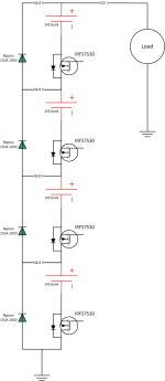
@ENNOID, by using bypass diodes https://drive.google.com/file/d/1CaRe9JpRlsMIjP-TPbW39DYUzdek7EPT/view?usp=sharing, the voltage on the FETs can be reduced? It appears no FET will be loaded with more than 58.8 - 0.5 = 58.3V, due to the bypass diodes, while the string voltage is 235V. So no need to have a FET that is rated for the string voltage. The bypass diodes also make it possible to switch off a problematic bank, while still powering the load with the remaining banks. Important in electric flight. What do you think of this design? Note that the IRFS7530 Rds is only 1.15 m.ohms. For a 300V string, the total Rds is 5.8 mO, which is probably as good as any contactor.
0 Power Pack (7).png
 
Maybe, I don't know, but it might works. This is a strange connecting scheme that I never saw before. You can try it if you want. The fets are on the BMS already, you would only need the external diodes. I'm using TOLL (to-leadless) package FETs on the BMS. They have even better performances than the D2pak your are pointing to.

I will order PCBs for a 15S-SS version this week. This would be better suited for your 14S modules. The 18S & 15S board will share 90%+ of component & design.
 
ENNOID said:
I will order PCBs for a 15S-SS version this week. This would be better suited for your 14S modules. The 18S & 15S board will share 90%+ of component & design.
Thanks, I would be interested in one or two 15S boards for testing. Can you put tabs on the board to allow for a discharge IRFS7530 to be added? Also circuitry for firmware control of the gate.

The bypass diodes will handle a lot of current if a bank is turned off, so I will install them direct on the module's output terminals with heatsink. I am using cheap 50A 1000V full bridge rectifiers. Two of the four diodes can be wired in parallel to give me 100A at 1000V, which is what my bank is spec'd (51V nominal, 59V max, 100A).

I went to your open source GitHub site and thanks for making your work open source. I can see the ASCII files for the schematics. But I don't know how to view it in diagram. What do I need to install (Windows) to see the schematics?
 
Can you put tabs on the board to allow for a discharge IRFS7530 to be added? Also circuitry for firmware control of the gate.

You haven't read my previous post right?

For your info, the latest kicad schematics are not on github yet...

Keep in mind, your connection scheme might work on paper, but this must be tested... practice & theory are different things and this setup might end up into smoke. Diodes that can dissipate 100+ watt of power @ 150A tend to be big & expensive...
 
Small update on the solid state BMS project. The size is now considerably smaller (40% reduction).

link for specs & details (still in progress):
https://www.ennoid.me/battery/bms-ss

After many board iterations and many changes to make the BMS more cost efficient & more compact. The board below is the one that should go out for final beta testing in a month or two:
18S-Front.png

Firmware & app are ready as well.
 
Hello ENNOID,

I see on your site that the solid state model only allows for 10A (20A) charging; won't that also limit regenerative braking? Cheers
 
Stiffler359 said:
Hello ENNOID,

I see on your site that the solid state model only allows for 10A (20A) charging; won't that also limit regenerative braking? Cheers

regen is not dependant on the charge port mosfet. its done by the main mosfets. so no.

i do have a question: has testing been done on actual current loads? like acually running 100A or more across the board for long durations like 1+ hour to see how the board deals with the heat without any active cooling?
 
Yes, regen on the dischare path has nothing to do with the separate charge path. 10A(20A) is conservartive with average Rdson FETs. So higher charge current is definetely possible with better FETs.

Not yet finalized high current beta testing, but it seems like it should hold at 100A according to the actual tests done so far. No much heating with 100A & 1oz copper thicknest 4 layer board for small period of time(lrss than a minute).

80A will definetely be ok with some natural cooling and appropriate cabling. 100A might be far stretched a bit without some heatsinking, but still realistic with 2oz in copper thick 4 layers board. High current traces are more than 1/2 inch wide at the narrowest with 0.001ohms in the discharge path. So, you can do the math according to some online tools & data on the subject.

The 150A continuous should also be possible by using 4 discharge fet & 2 shunts. Discharge path would be slightly above 0.0005Ohm in this case, but we will see.
 
i understand the math, but the problem is that board construction and final assembly is not as perfect as the math makes it out to be, so its always good to test if it actually reaches it ratings and if you might need to tweak some things. especially when getting near those triple digit amp numbers imperfections start to add up.
also having temperatures for different amp ratings is quite important for long duration high current applications like in a decently sized vechicle or a off grid solution.
 
Yep, and as I said. it seems to works well at 100A continuous so far. At the end, there are many other parameters outside of the BMS that I cannot control and that will have a direct impact on the lifetime of the product.

If you think that it would be preferable to have some datas, official documentation, or even videos that shows off the BMS capability, that is a good idea. I could eventually work on this later this year.

Meanwhile, I highly doubt the chinese BMS that you are probably using currently have any similar datas as well to proove their capabilities. 😉
 
ENNOID said:
Yep, and as I said. it seems to works well at 100A continuous so far. At the end, there are many other parameters outside of the BMS that I cannot control and that will have a direct impact on the lifetime of the product.

If you think that it would be preferable to have some datas, official documentation, or even videos that shows off the BMS capability, that is a good idea. I could eventually work on this later this year.

Meanwhile, I highly doubt the chinese BMS that you are probably using currently have any similar datas as well to proove their capabilities. 😉
most of the bms that i use i have to modify in some way or another and test anyway. everything from replacing the mostfets with contactors or other fun stuff simply because there is no single bms that can do the wide varity of applications i make batteries for.
i refuse to buy a overtly complicated bms that costs way too much and has features nobody give a shit about so its cheaper and more productive to use just 1 or 2 types and modify them to suit the needs.
and yes, i do have to test them at full capacity and in various cases i still need to change things so it works "as advertised". there are not many bms that can actually handle a 30S battery at 400A continuous for example.
 
Ok, thank you for being so positive about a very nice product that is indeed needed for most serious EV applications.

i refuse to buy a overtly complicated bms that costs way too much and has features nobody give a shit

Seriously flippy, you don't need to post anything negative/offensive here. I'm not here to do bashing on anyone's product or services.

Maybe you should give my BMS a try at least. It might end up being useful for your apllication. 150$ for a BMS that can handle & protect the power of a small motorcycle or very powerfull ebike with a battery pack costing more than1k$ is not overly expensive IMO.

A lot of peoples are complaining about BMS in general because of the terrible dirt cheap chinese BMS on the market mixed with the horrible conventional method of building DIY battery packs and the long history of failure related to BMS. The time will come that someone will fix this I hope. It might be me or not, at least some people are trying to fix this problem instead of complaining...
 
ENNOID said:
Seriously flippy, you don't need to post anything negative/offensive here. I'm not here to do bashing on anyone's product or services.

this was not meant for you, but for the current market of "high end" bms models you can buy. i dont need crap like "canbus interconnected daughterboards" or some shit that lots of current options love to peddle where you spend tens of dollars on a single daugherboard thar does nothing exept have some blinking lights and a resistor. you dont need canbus for that bullshit. even the lowest model of arduindo can or should be able to do everything and more that you could ever want a bms to do. it really does not need to be more complicated then that.
i should not need to have a 500 euro canbus cable to be able to talk to the bms to change a simple setting, a 2 euro discount bin usb cable should be enough. if i want it to talk to a controller like sevon then fine, but it should never be mandatory in order to program the blooding thing. we have the technology. we can do better, faster, stronger. :mrgreen:

and i love your iterations so far. reducing size, part count, single direction connections and so on.

ps: is there an option to add a metal/plastic "shield" between the common and positive? if you have regular crimp connectors on wires you will twist the connector when thightening and then they can turn and touch because they are so close. some form of insulated shield between them could prevent "mishaps". a simple dead (not connected to anything) metal bus bar between them with a layer of kapton would already do the trick. same applies for the fuse and battery negative spacing. they are AWFULLY close and just waiting to short when you are trying to manhandle the cable to it.
 
Well, CAN bus will prove to be useful if properly implemented. Watchout at the VESC BMS that will be soon released as well. Many cool things can be done over CAN bus, like throttling, soft shutdown, charger control, etc.

If I was a small ebike manufacturer giving a warranty or a DIY guy with a quite expensive battery pack, I would like to have a final product that has a BMS that can really protect the pack against any conditions. For instance, having an ESC that can be informed by the BMS over CAN bus that the limits have been reached on temperature or cell voltage, so it can throttle down regen or discharge respectively. How can you know without communication between the BMS and the ESC that one cell in the pack is under the minimum voltage limit or that the pack temperature is above a given limit? This is a complex topic, but this can be done with my BMS over CAN bus. I'm not claiming it is perfect, but the goal is to get a good score on that topic. Some car manufacturers have figured this out long time ago. I think it is time for DIY or small companies to also have a proper BMS.
 
i am not saying it should not have cool features and expensive/complicated connection options, it just should not depend on them in order to get the bloody thing to work. :wink:
 
Agree, BMS should not depend on it to operate at the basic level, but is nice to have on a high end build.

For the main wurth connectors quite close to each other, yes this is something that must be handled carefully during assembly. That is the result of reducing the size so much and it was also a consequence of going above 15S...I had no choices, but to go with low side current sensing thus putting all high current path on the same side of the PCB & quite close to each other, but not excessively IMO. I find those wurth connectors quite convenient and could not go without them.

Another option would be to supply the BMS without the wurth connector & using wires soldered directly to the PCB & connected to external XT90 or similar. I included one additionnal pad visible for this option and allow to still have the fuse mounted. The other unpopulated wurth pads would then be soldered.

I also tried to fit XT90 directly onto the PCB, but they would take too much space and was unable to make it convenient, so I gave up on this idea.
 
Small update:

I updated the website this morning with some 3D .STEP files, dimensions & pinout of the SS board or the ones interested. Also added some other docs info.

I will do do a short video to show how the desktop app works with the BMS and also need to create a basic troubleshooting guide. (Long overdue)

I received the new PCB set & also been able to order the 160 x 18S IC that were back orders & frankly hard to get. Should have them by next week. I’m still on track for delivering the first units at the end of March.
 
Back
Top