I gutted a E+'s "in hub" controller - strange results

Firedog

10 W
Joined
May 26, 2017
Messages
92
I was given a 2010 era E+ bike several years ago. It had rear direct hub motor with the controller inside and a similar sized front hub containing 30 NiMH "D" cells (36v) and a very complex charge boards. When the bike worked, the performance and features were really good.

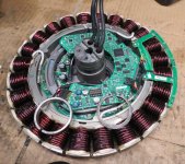
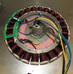
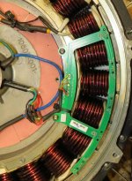
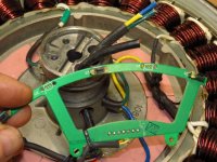
To improve it, I got rid of the front battery hub and switched to Lithium batteries. I had to keep charge boards for the bike to work. Mostly it worked well, but every so often, the display reported errors that couldn't be cleared. I finally gave up trying to solve the problem, and gutted the controller from the motor. I connected proper size leads directly to the 3 phase wires and hall sensors leading to an external controller. I've done this on Stromer and other hubs that have the controllers built inside. No problems and great performance using the external controller.

I expected the same results with the E+ but instead I get much a much reduced current using 3 external controllers. 17a, 30a and 35a max at 54v deliver only a maximum of 12-14amps. Same controllers on any other geared or direct hub motor deliver the rated amps.

Anyone want to try an explanation? I'm curious.
 

Attachments

  • IMG_3730.jpg
    IMG_3730.jpg
    196.5 KB · Views: 1,298
  • IMG_3732.jpg
    IMG_3732.jpg
    166.2 KB · Views: 1,298
When you say limited performance, can you give us more detail. Did it run smoothly without power, did it jutter around, what do you mean limited power?

Also, how do you know your phase wire / hall sensors were in sync?

:D :bolt:
 
Windings look darker then usual, you could have cooked the motor.
How does the motor smell?
I like to buy sensored/sensorless controllers so you dont have to deal with the right combo of phase wires and hall wires(sensored)
 
Firedog said:
I expected the same results with the E+ but instead I get much a much reduced current using 3 external controllers. 17a, 30a and 35a max at 54v deliver only a maximum of 12-14amps. Same controllers on any other geared or direct hub motor deliver the rated amps. Anyone want to try an explanation? I'm curious.
IIRC the EMS E+ did NOT use a three phase motor. The Tidalforce that it was based on used a 7 phase motor. I am not sure if the E+ used seven phases or some other number, but when I looked at it years ago I thought it would not be easy to convert.
 
JackFlorey said:
IIRC the EMS E+ did NOT use a three phase motor. The Tidalforce that it was based on used a 7 phase motor. I am not sure if the E+ used seven phases or some other number, but when I looked at it years ago I thought it would not be easy to convert.

Tidal force is 7 phase, but I've always understood Electric Motion System E+ used 3 phase. There are 24 coils with 3 wires feeding them so 7 doesn't work. But 6 x 4 = 24. Could it be 6 phase and with only 3 phase wires? The max current, I see using 3 phase controllers is roughly half the controllers' ratings.

markz said:
Windings look darker then usual, you could have cooked the motor.
How does the motor smell?
I like to buy sensored/sensorless controllers so you dont have to deal with the right combo of phase wires and hall wires(sensored)

No odors or discolored wiring. Everything was sealed and pristine. The 3 controllers I tested are sensored/sensorless. They also have a "learning" mode used the first time the controller and a motor are paired. Connect the 2 white wires and the motor starts, sometimes backwards. If so, disconnect/re-connect and the it goes the other direction. In a couple minutes the controller discovers, if there are sensors, the phase angle and sorts the out the phase wire order. Disconnect the the white wires and the controller remembers the settings.

e-beach said:
When you say limited performance, can you give us more detail. Did it run smoothly without power, did it jutter around, what do you mean limited power?

Wheel up in the shop, they all ran smoothly after the "learning" procedure. On the street, still smooth, quiet, no start jerk, but only about half the normal amps and power during hill climbs. One other thing, the throttle response was pretty much on/off: difficult to hold....say 5 amps. Also, these controllers have 3 power level that reduce power at various speeds. So level 1 reduces current if the bike is going over 20mph even if the throttle is full on. That didn't happen using the E+ motor. Full throttle, full amps, even if speed high. The controller gets it's speed info from the Yellow phase wire. If it's getting half the pulses expected at 20mph, it will think the bike is going 10mph and not cut back power.

I'm ok scraping the motor, but it would be nice to understand what's going on.
 
3 wires and 24 poles, I am calling it 3 phase. If I am wrong, feel free to let me know. :oops: :lol:

However, it sounds like one of those "could be" situations.

Could be that your controller learning didn't learn exactly and your phase / hall timing is still out.
Could be a bad hall sensor.
Could be your throttle is bad.
Could be that your battery sags on the hills.

So what do you think. Could it be any of those problems?

On the other hand, where do those other little black wires go to?

:D :bolt:
 
Best guess is the halls are not in the usual 120-degree positions, and instead are 60-degree. Some controllers simply don't support that at all, and some just don't do it well, and some have to be manually set to the right way.

IIRC if you have a 60-degree hall setup, flipping the center sensor over may make it work with a 120 degree controller. Not certain about that--you'd have to poke around to find the old thread with that info. :(

Alternately, you could just move the outer pair of sensors to the unoccupied set of holes in the PCB (or populate them with spare sensors and ensure the outer pair are disconnected from the wiring; this is probably done by moving the signal wires for them to the unoccupied pads in that separate area of the PCB).
 
amberwolf said:
Best guess is the halls are not in the usual 120-degree positions, and instead are 60-degree. Some controllers simply don't support that at all, and some just don't do it well, and some have to be manually set to the right way.

I tested the motor with a motor/controller tester before connecting to any controller. Phase LEDs lit normally. All the hall sensor LED's lit too, but this is the first time I've seen the 60degree LED also light. The controllers I used states "Phase angle: self study" so I assume the controller would adapt to either 60 to 120.

The physical location of the hall sensors is on that green PC board; the green and yellow at each end; the orange (I changed to blue) in the center. Since there are 24 coils, each fills 15degrees (360/24) and there is 2 coils between halls, the physical angle between halls 30 degrees. I'm guessing that electrical angle and physical angle are different. There must be an equation that expresses the relationship.

When I connected the cable to the halls, I was concerned that the order (yellow/(org ->blue)/green) is different than found in connectors and on controller boards (yel/grn/blu). I check a lot of photos of open motors and that seems to be standard so I didn't swap any.
 
Firedog said:
I tested the motor with a motor/controller tester before connecting to any controller. Phase LEDs lit normally. All the hall sensor LED's lit too, but this is the first time I've seen the 60degree LED also light.
Then that probably indcates it is indeed a 60degree hall motor. And I would almost guarantee that the inner two hall positions, if used instead of the otuer two, would make it a 120 degree.

If i were doing this experiment with this motor, thats the first thing I would try, is to install a new pair of halls into those spots (assuming there are matching spaces in the stator for the hall itself), move the hall wires to the corresponding pads, and retry it on the motor / controller tester, to see if it still lgihts the 60 degree light. If not, I'd put it on the controller and then see if it works more llike I'd expect it to.

The controllers I used states "Phase angle: self study" so I assume the controller would adapt to either 60 to 120.
I'd hope so..but there's no guarantee they'd get it right. ;) Some self-learning controllers for phase/hall combo also don't work on some motors. Some have a jumper or pad that can be soldered to tell them if it's 60/120, on the circuit board inside the controller. Some can't do 60 degree at all. (all but one that I have had did do 120 degree fine...that one only did 60 degree and probably came wiht a specific motor, but it was secondhand so I dunno).

The physical location of the hall sensors is on that green PC board; the green and yellow at each end; the orange (I changed to blue) in the center. Since there are 24 coils, each fills 15degrees (360/24) and there is 2 coils between halls, the physical angle between halls 30 degrees. I'm guessing that electrical angle and physical angle are different. There must be an equation that expresses the relationship.
They are different, though I have no idea how to figure out one from the other. :oops: There's a thread around here somewhere talking about it...but I oculdn't find it in a minute or two.


When I connected the cable to the halls, I was concerned that the order (yellow/(org ->blue)/green) is different than found in connectors and on controller boards (yel/grn/blu). I check a lot of photos of open motors and that seems to be standard so I didn't swap any.
There's no real standard. you might even find two "identical" motors (or controllers) that have the wires in a different order. So unless the controller has "self learn" where it figures out the right combination on it's own, then it would require manual swapping of wires to figure out the right phase/hall combo...which can only be done if the right hall/phase angle is first determined and used.
 
I missed doing the most basic test. My external controllers also run sensorless motors: unplug the halls and the E+ is sensorless motor. In the shop, wheel up, I connected only the phase wires. Did the "learning" routine to get the correct direction and let the controller know the halls are gone. Looked good, so ended "learning". Good start with just throttle in the shop, seemed faster than with halls.

On the street, I first pedaled to ~5mph, then applied throttle; shuttered badly. Pedaled to ~10mph then throttle; it took off beautifully at full rated controller amps; smooth and quiet. The controller also did it's power saving feature of reducing current above 20mph in low. I expect that will also function in power setting medium and high.

My conclusion: My E+ hub motor is a good, strong 3 phase motor. Hall phase angles are wrong, at least for my controllers. I think it is safe to conclude the timing is not 120, but that doesn't necessarily make it 60 especially since my controllers, designed to "self learn" 60 or 120, didn't work. The designers of the E+ knew the motor would only be driven by their in hub controller and were free use any angle they thought best,

Amberwolf, Is https://endless-sphere.com/forums/viewtopic.php?t=2472 the "60/120 degree" thread you referred to?
They discuss converting 60 to 120 or 120 to 60 by physically turning the center hall upside down and swamping the position of the
outside ones. Does that make any sense to you?

One guy in the above thread posted posted a very interesting link
https://community.parker.com/technologies/electromechanical-group/w/electromechanical-knowledge-base/174/hall-sensors-60-vs-120degrees
He says by electrically inverting the signal of the hall #3, converts 60 to 120 and shows scope traces. That might be worth a try. Can you suggest an inverter chip?
 
Firedog said:
He says by electrically inverting the signal of the hall #3, converts 60 to 120 and shows scope traces. That might be worth a try. Can you suggest an inverter chip?
If 5V is available (which it probably is if they are the usual Hall sensors) a 74LS04 or 74LS00 will work fine.
 
Firedog said:
I think it is safe to conclude the timing is not 120, but that doesn't necessarily make it 60 especially since my controllers, designed to "self learn" 60 or 120, didn't work. The designers of the E+ knew the motor would only be driven by their in hub controller and were free use any angle they thought best,
True; I poked around the intarwebs and found nothing documenting it (not really anything except this thread that even shows the guts!).

It is even possible that the five hall positions on that board are for it to also be used with a five-phase motor and controller, but I doubt it...I can't imagine that they'd do that then have to design a 3-phase controller that sort-of used part of the five-phase hall timing. ;)

It's more likely that the two outer and inboard hall positions correspond to 60 and 120 degree timing for that specific motor, and that hte ocntroller in there is just setup for whichever the outer pair is for (probalby 60).

But I R Not A Motor / Controller designer (my only degree is in ancient electronics repair :lol: and not much used), so I'm only guessing based on previous hacking experiences. ;)


Amberwolf, Is https://endless-sphere.com/forums/viewtopic.php?t=2472 the "60/120 degree" thread you referred to?
They discuss converting 60 to 120 or 120 to 60 by physically turning the center hall upside down and swamping the position of the outside ones. Does that make any sense to you?
It does; I think I described that as a possibility previously (though I think I forgot about swapping the wires between the outer ones, because in your case you have auto-learn so it wouldn't matter). And yeah, i think that is the thread--it seems familiar. :)


One guy in the above thread posted posted a very interesting link
https://community.parker.com/technologies/electromechanical-group/w/electromechanical-knowledge-base/174/hall-sensors-60-vs-120degrees
He says by electrically inverting the signal of the hall #3, converts 60 to 120 and shows scope traces. That might be worth a try. Can you suggest an inverter chip?
As Jack said, the 74LS00 or 74LS04 would work if it's 5v supply. If it's not close enough up to 5v, the 74AC00 or 74AC04 (or ACT) might work. If it's well over 5v, the 4000 / 4004 might work
https://en.wikipedia.org/wiki/Logic_family#Monolithic_integrated_circuit_logic_families_compared
or you can use a transistor inverter which only takes two small parts you may even be able to salvage from unused electronics you have laying around:
DKXKm.gif

Mmm...no, wait--that won't work unless there is already a pullup resistor on the output of the hall sensor (because the hall doesn't output anything, it only grounds the output wire, so without a pullup (usually in the ocntroller, not the motor), there's no toggling signal. Mmmm. I'll think and poke around.

Mmm..brain not operating. All you have to do is add a second resistor (5k-10kohm) from teh base input (A) to VCC (hall power), and it does the job.
 
I use the battery powered ebike tester to compare the hall signals of my E+ hub motor to a Voilamart 800w that has 120 degree timing. Both hubs have 6 unique patterns as you slowly rotate the wheel forward which then repeat. The left set is the E+, stock. Center set the Voilamart hub. Right set is the E+ if the blue hall's output is inverted. Invert blue and it's a perfect match!
Hall sequence comparison.jpg

So, I built an inverter circuit for the blue hall using a 74lS00 and a 10k pullup resistor between the hall's + and its output. The 1st try I used the same red wire to supply voltage to the inverter and the halls. The battery powered tester's voltage is 4.75v and testing the sequence gave the correct results (blue was now inverted).

I connected the motor to the controller (with Blue hall inverter) and got the same poor low current results. The + voltage the controller supplies to the hall is 4.35V (below 4.5v min for a 74LS00). So I opened the controller and found 5V pads (actually 4.9v) and brought that to the Vc of the 74LS00. See my exact wiring below.
inverter circiut.jpg

That didn't fix it. I plug the in the tester, keeping the controller's 4.9v to the 74LS00's Vc but the tester's 4.75v to the hall sensors and the blue output light stays on continuously.

Is it time to give up?

Would anything bad happen if I switched the hall's red + wire to the controller's 5V pad and feed both the halls and the inverter 4.9v?
 
Firedog said:
I connected the motor to the controller (with Blue hall inverter) and got the same poor low current results. The + voltage the controller supplies to the hall is 4.35V (below 4.5v min for a 74LS00). So I opened the controller and found 5V pads (actually 4.9v) and brought that to the Vc of the 74LS00. See my exact wiring below.
inverter circiut.jpg

That didn't fix it. I plug the in the tester, keeping the controller's 4.9v to the 74LS00's Vc but the tester's 4.75v to the hall sensors and the blue output light stays on continuously.

I'm on the tired side at the moment and my brain is processing slowly and not so great, so forgive the question:

It did work on the tester correctly, right?

But now it doesn't, *after* having tested it on the controller?

If so, I think the problem might be the controller's internal pullup on the blue line interfering with the NAND gate's output, since this NAND isn't open-collector output like the hall itself is (whcih I didn't think about when specifying which chip to use :oops: :cry:). (The 74LS01 and 74LS05 and 74LS06 are, though.)
https://en.wikipedia.org/wiki/List_of_7400-series_integrated_circuits
Since it isn't, then the controller's internal pullup resistor from the signal line to the 5v line might be a low enough resistance (vs the tester's pullup that did work) that it is causing problems with the NAND's output stage.

If you disconnect the controller from power and wait a few minutes to ensure all the caps are discharged, then you can disconnect the controller's hall signal wires, and measure from each one to the controller's hall-5v line. That should give you the controller's pullup resistance. If it's really low, it might be pulling up "too hard" and when the NAND tries to pull down it might overload the NAND's output stage and damage it. Fixing this would require changing the pullup resistor in the contorller on that specific hall signal line to a (much) higher resistance (or removing that pullup resistor from the board entirely, which would be better for this specific situation), and then using a different NAND gate on that chip (since the first one might be damaged).

Also, you can just parallel both inputs of the NAND gate together to run them both off the hall, since that just turns it into an inverter (like the LS04/5/6). ;)


Firedog said:
Would anything bad happen if I switched the hall's red + wire to the controller's 5V pad and feed both the halls and the inverter 4.9v?
Nothing I know of--the only potential issue I can think of is if the controller's hall power is run thru some component (diode, etc) that drops the voltage not to drop the voltage, but to keep noise from the motor phases (induced into the hall wiring) from feeding back into the controller's other 5v components and causing glitches or other issues.

Otherwise there's no reason to not power them from as high a voltage as they'll normally handle (not right at the top edge of their spec, if possible). Higher voltage on supply and pullups generally means higher signal-to-noise ratio in operation. :) But 5v is the typical standard for those 74LS devices, so stick with that for this circuit. Don't know which halls you ahve but they often work up to 24v, depending on specific model.
 
amberwolf said:
It did work on the tester correctly, right?

But now it doesn't, *after* having tested it on the controller?

The LEDs flashed in correct order the with the testers 4.75v powering all 3 halls and the 74LS00 inverter.
When I used the controllers 4.9V to power only the inverter, the blue hall LED was locked on. The other 2 still flashed. (the 4.75v of the tester was powering all 3 halls.)
When I return the inverter's Vcc to the 4.75v from the tester, the LEDs again flash in the correct sequence.
I also connection the 4.9v to all the halls and the inverter, Bike behaved same as if the stock halls (60*?) were connected directly (Smooth start, ~50% power, little throttle control, no power tapering at speed). Of course no way to connect the tester.

Probably best to let this problem stew for a while. I'm fuzzy headed right now. Sometimes a few nights sleep helps.

I'd run the motor sensorless with one of these controllers except smooth start requires so much speed. Restarting on a hill would be impossible. I have a old 72v45a Crystalyte sensorless controller I removed from a customer's bike who didn't like that much speed or spending the $ for a battery to match. It started pretty darn smooth without sensors. I'd probably cut one of the 2 shunts to see if I could fool it into a more decent behaving 72v22a setup.
 
Why not just replace the blue Hall sensor and see if solves your problem?

:D :bolt:
 
The sensor is working....it's just that the signal is opposite to what the controller needs to see. (meaning its grounded when it needs to be powered, and vice-versa).

Replacing the sensor won't do anything to fix that (unless there is a version of the sensor that has an inverted output; I don't know if there is). PHysically flipping hte sensor over might work, but the hole it has to go into in the motor might only be shaped to fit it the way it is now.

The problem at this point is simply inverting that signal in a way that the controller's input will accept without interfering with it.
 
Thanks to amberwolf and others, but I'm going have to give up tying to use and external controller work with the E+ hub. It would have been really nice to come up with a simple method to convert 60 degree hub motor to 120. I think that's still possible, but I think there are other things going on with the E+'s we don't understand. I think amberwolf is right that adding inverter circuit, powered by the controller some how locks the hall's the output high. I tried connecting a 10k resistor to hall's output and Vc (pullup) and to ground (pulldown) with no change in the bad results. I could do that from outside the hub. I wish I had tried to turn the blue hall upside down, but I'd have to open and close the hub and it doesn't look like and easy task once inside. I've added a close up of the hall's. Interestingly, the hall pc board has pads for 5 halls, but only 3 are populated. I also checked and none of the halls are installed upside down.

I did try to run the E+ hub motor sensorless using an old Crystalyte 72V45a sensorless controller that worked surprising smooth on 2 other hub motors. I tested each of the 6 combination of phase wire connections to find the 3 that go the right direction. All 3 had a brief jerky start, then smooth on the bench; so I test rode all 3. Pretty much all the same, really rough starts which could be smoothed slightly by backing way off the throttle. When I pedaled hard to get speed, it still never smoothed out. The E+ hub has only 24 coils. I don't think that's a reason for not being able to operate sensorless. Right?

It's time to move on.
 

Attachments

  • Hall.jpg
    Hall.jpg
    143.9 KB · Views: 1,027
Was an interesting experiment, anyway. ;)

Firedog said:
nterestingly, the hall pc board has pads for 5 halls, but only 3 are populated.
Yes. that is what I was referring to when I said it was possible that simply adding sensors in the unpopulated places and then moving the signal wires from the pads that go to the two outboard pads to the two inboard ones instead would probably change the hall timing to 120. No guarantees...but it seems likely.

Additionally, it is possible that the empty sensor positions are there for sensing for the same board to be used on a five phase motor, but that's unlikely. Other possibilities as well, but the simplest is usually easiest, and that's that it's for 60/120...maybe. ;)


I did try to run the E+ hub motor sensorless using an old Crystalyte 72V45a sensorless controller that worked surprising smooth on 2 other hub motors. I tested each of the 6 combination of phase wire connections to find the 3 that go the right direction. All 3 had a brief jerky start, then smooth on the bench; so I test rode all 3. Pretty much all the same, really rough starts which could be smoothed slightly by backing way off the throttle. When I pedaled hard to get speed, it still never smoothed out. The E+ hub has only 24 coils. I don't think that's a reason for not being able to operate sensorless. Right?
Well, it's likely that it has a different inductance (lower? ) than the other motors, and that may cause grief with some controllers. SInce it has less coils (by maybe half?) vs typical DD hubs, it may not run as smoothly anyway, and startups can be expected to be jerkier/rougher than higher-pole-count motors would be.


But for now on the right side of my heavy SB Cruiser trike, I am using an ex-Stromer Ultramotor (like those on A2B's) that is built similarly to the E+ hub, with a low pole count, and it's pretty smooth and very quiet with a generic controller, though I don't think that controller works sensorless (cant' remember if I tested that or not), so don't know how smooth it would be that way. The UM's halls are already installed in 120 degree spacing, so I didn't have to messa round with that, thankfully.
 
Can't seem to leave a problem alone.

I looked close at the hall mounting. All are mounted with the bevelled edge away from the magnets. That's right side up, I think.

The motor has 24 coils and 27 magnets. Stock hall spacing is 2 coils, but with 5 hall pads available, the spacing can be changed to 1 coil.

Here's a tutorial on Hall timing. https://www.digikey.gr/en/blog/using-bldc-hall-sensors-as-position-encoders-part-1

I think there is enough information to be able to figure out a hall mounting resulting in standard 120 timing.
I'm having a hard time with it.
 

Attachments

  • Halls upside down.jpg
    Halls upside down.jpg
    125.4 KB · Views: 982
  • IMG_3747.jpg
    IMG_3747.jpg
    115.7 KB · Views: 982
  • coils and magnets.jpg
    coils and magnets.jpg
    200.5 KB · Views: 982
If I had one of these, I'd just add two more halls in those empty spots, and move the outboard halls' signal wires over to the two empty pads, just to see what it does. :)

I'm not all that great at following "math" to determine where to put stuff like halls...when I added halls to a powerchair motor to test it with an ebike controller, I put them in a physical 120 degree triangle, glued into the stator slots, and it worked. I might've just gotten lucky :oops: ...but it was simple to try, so I did. :lol:

Afterwards, because i had one, I played around with Burtie's Timing Adjuster on the hall signals to see what retarding or advancing them might do, though I don't recall what the results were; it's in my Powerchair BLDC Motor thread somewhere around here.


BTW, I coudln't see this in previous pics, but in your recent IMG_3747.jpg the black rectangle with 103 on it is a 10kohm pullup resistor. Those are usually on the controller end of things, not in the motor, so if it helps troubleshoot, you won't need the pullup resistor added to your hall signal before the inverter. The brown rectangle is a "decoupling capacitor", probably in the 0.01uf range, meant to help with noise on power/ground lines.
 
This E+'s hub motor has 30 magnets and 24 coils with 3, 40L hall sensors with 2 coils between each hall. Rotating the motor shows 6 unique hall signals using an LED ebike tester. The pattern repeats 15 times during a 360* of the wheel. The stock pattern includes all three halls on at the same time which is normal for a 60* motor but not for a 120* motor. The tester has a 60* LED which is lit using the stock set up.

If I had one of these, I'd just add two more halls in those empty spots, and move the outboard halls' signal wires over to the two empty pads, just to see what it does. :)

First I tried keeping the empty spots and physically turning the center hall upside down. That inverted the center (blue) hall's output and made the 6 signals identical to 2 other motors I have on hand. Both, non E+ motors repeat the 6 unique combinations 23 times every wheel revolution. I believe that those motors must have 46 magnets.

Next I followed Amberwolf's suggestion and moved the outside halls in so the separation of the halls is only 1 coil. Since the center hall was still inverted, the pattern was back to what I think is for a 60* motor. I flipped the center hall back to stock and got the same results as the 2 working motors.

Looking good, so I re-assembled the motor, mounted it on the bike, connected it to a 54V30 amp controller with the "learning" feature discussed previously. Seemed good on the bench, but again had terrible start shutters on the road. If I pedaled or coaxed to over 10mph, it smoothed out and had good power and 25+ amps. Acting much like my test without any Hall's connected.

I certainly don't understand the problem, and I can't think of anything else to try. My controller states it learns the phase angle of the motor but not specifically that it works with a 60* motors. Perhaps a controller that is designed for 60* motors?
 
Firedog said:
This E+'s hub motor has 30 magnets and 24 coils with 3, 40L hall sensors with 2 coils between each hall. Rotating the motor shows 6 unique hall signals using an LED ebike tester. The pattern repeats 15 times during a 360* of the wheel. The stock pattern includes all three halls on at the same time which is normal for a 60* motor but not for a 120* motor. The tester has a 60* LED which is lit using the stock set up.
The only thing I can think of is that because this is a lower pole-count motor than the typical hubmotor, it affects how the controller operates it (more poles usually means smoother operation, though I forget why).


I can't think of anythign else to try either, unless there are some controllers that work better on lower pole count motors than the ones you have.

At this point I doubt it has to do with 60 vs 120; youv'e eliminated that in multiple ways, AFAICT.

:(
 
Amberwolf,
I just watched Justin's video on Salvaging a BionX hub motor with bad internal controller. https://www.youtube.com/watch?v=Wc8OJtFRUng The BionX has 24coils/22magnets/halls every 8 coils (120degrees). He used a Phaserunner3 controller, software and a Window's computer to automatically optimize timing. It was smooth on the bench and I'm sure he would have noted any issues on a bike under power. (Thank God for Justin)

The E+ motor has 24 coils/30 magnets and halls separated by 2 coils and tested 60 degrees. We tested the motor with the halls separated by only 1 coil and that tested 120 degrees. I used several generic controllers with "auto learn" function that seem smooth on the bench, but no combination worked smooth under load at less than 10mph.

Question:
1. After all we tried, do you think a Phaserunner3 controller and software would smooth out the E+ motor? Probability?
2. My niche in the ebike's world is low cost kits so I've stayed away from expensive hardware and I don't need the power of the Phaserunner3. Is there other smaller programable controllers that have the same capabilities or use Grin's software?

I hate leaving a problem without finding a solution or at least fully understanding the problem.
 
The motor probably needs more phase amps than normal due to the low pole count.
What are your phase amp/battery amp settings?
 
Back
Top