LewTwo
1 MW
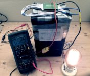
Well I was warned ( markz, https://endless-sphere.com/forums/viewtopic.php?t=110214 ) but I did it anyway. I purchased a “Open Box” battery off EBAY. It was an “imotorbattery” branded LiFePO4 48 volt 15 amp hour battery. The Ebay listing indicated that it had been tested. Turns out the vendor (name omitted to protect the guilty) had no clue how to test a Lithium-Ion battery. Yep it was defective. I could charge it to 58 volts but once the charger was removed it dropped down to 54 volts in mere moments. Two capacity tests (2 Amps) shut down after 3 hours with a measured capacity of about 7 Amp Hours. I believe the technical term for this condition is “Tango Uniform”.
So I contacted the vendor and informed him of problems. It took several days before he acknowledged that there might be a problem and that I had 30 days to return it. How says I. The battery is rated at 720 watt hours and weighs 17 pounds. It exceeds the 300 watt hour limits for a consumer to ship a lithium ion battery (UN3480) via FedEx, UPS and/or DHL. He instructed me to open a Ebay return case and that he would take care of it. For my trouble I got a USPS return label. USPS limits are even lower than the common carriers (100 watt hours). It seems that this vendor is “willfully ignorant” of any regulations for shipping Lithium-Ion batteries. I should note at this point that the vendor shipped the battery to me via UPS ground without any lithium warning labels. If I can not legally return the Ebay Sale item then the vendor is under no obligation to issue a refund (I am still contesting that). I used the USPS label to send him printed copies of various UPS, Fedex, USPS and Fed regulations regarding Class 9 Hazardous Cargo.
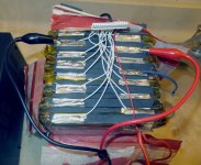
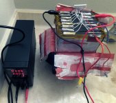
I reluctantly accepted that I was likely going to have to eat my loses. I had done a number of layouts for cylindrical cells (18650, 26650, 32650) but had not found a good match for the battery dimensions. Eventually I cut into the battery to see if I could discover the problem. Some very fine surgical slicing and dicing with a sharp utility blade managed to reveal the first big surprise: this is a pouch (polymer envelope) battery … a huge, glorified RC battery encased with cardboard and shrink wrap. A bit more careful cutting, so as not to accidentally nick one of the pouches, allowed me to fold back the upper third of the case (not much of a case). It appeared that someone in manufacturing neglected to fully seat the 16 pin balance connector to the BMS board. The last cells in series had a intermittent connections.
So next I broke out the multimeter and checked the voltage levels for each cell:
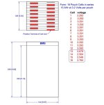
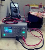
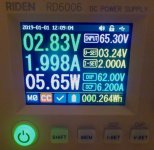
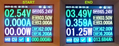
Note the values for cells 13, 14, 15 and 16. I decided to use my variable 30 volt 5 amp bench power supply to manually balance the individual cells followed by bulk charging the battery. Of course charging a 60 volt battery with a 30 volt supply is a bit of a challenge. I used my solder gun to add a new 16 AWG wire to the junction between cells 8 and 9. Then I charged each individual low voltage cell to bring them close to same voltage. Next I charged that block of four cell to bring them up to the voltage of the other four cell blocks (13.16 volts). Lastly I needed to charge the two banks of 8 cells to 29.2 volts … or I planned to. Turns out the little bench supply did not have sufficient mojo for the task. After setting it to 29.5 volts and 3 amps it showed 0 Amps being delivered when the output was turned on. The multimeter showed no volts and 12 milliamps from the power supply terminals :-( Tacklife is shipping a replacement Power supply I am going to derate that replacement PS to 24 volts and hope it does not fail.
Moving on to Plan “B”: All the previous stuff was done with the BMS out of circuit. I wired the BMS back in being certain to fully seat the balance lead connector. Then I connected up the original 58 volt charger and plugged it into house current (110 VAC). Now to wait for the green LED. I have no love for watching grass grow, paint dry or electrons moving about in the ether. A watched pot never boils and a watched charger does so excruciatingly slowly.
13:30 hours … time to take a nap … 16:30 hours
Well the Green LED is lit but the balancer leds keep flashing on and I am only seeing 56.3 volts from end to end. One LED in the middle is ALWAYS lit and the last four (which correspond to the problem children) never light up … h’mmm, I need to take out the trash and watch a youtube video
This is signalland BMS. Not much found in the way of documentation but I did find a video:
https://youtu.be/6i8i6h1LkBw
17:30 hours ….
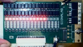
Well the LED’s have stopped blinking. The first 12 LEDs are on and the last four are off. So I wait for all the LED’s to turn off and then check the cells again. The first 12 are sitting between 3.164 and 3.121. The last four are siting at 2.925 to 2.920. I rechecked the first cell and the voltage had dropped while I was testing from 3.163 to 3.144. Either the cells are self discharging or the BMS is draining the battery.
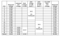
That last column is after the battery was bulk charged with the BMS. Those voltages are actually lower than the starting voltages.
I unplugged the BMS again. My suspicion is I either have a defective BMS or 4 defective cells or both. I am going to place my bet on the BMS and cut it out. That should allow me to directly charge the battery from the charger (I hope) …. after I manually balance the cells again. Oops, I can not do that as the power supply is now Tango Uniform as well. Well the cells are fairly close (about 0.15 volts). H’mmmmmm …. my low voltage problems all went away after I got rid of the BMS. The OEM charger was happy to pump some power into the battery without the BMS sitting in the middle.
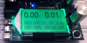
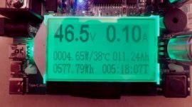
Time for capacity test. I am using a low voltage cutoff module between the battery and the capacity tester. That is set to shutdown at 40 volts. So it is off and running. Did I mention something about watching paint dry ….
After 5 hours and 18 minutes the pack voltage was down to 46.5 volts having drawn 11.24 Amp Hours (578 wHr). Unfortunately the last four cells were down to 2.1 volts while the 8 front cells were sitting around 3.2. Boys and girls THIS is why you have a BMS.
The Autopsy conclusion is Dead On Arrival caused by critical organ failure.
Replacement LiFePO4 poly cells in this size run about $40 each (plus shipping and tax).
https://www.batteryspace.com/High-Power-LFP-Polymer-Cell-3.2V-15Ah-87122200-2C-48Wh-30A-rate.aspx
I am dead in the water until I have a working variable voltage power supply. I did order a new Daly 16S LifePO4 25 Amp BMS (common port for charge/discharge) via EBAY and a slow boat from China. I will likely try one more time to resurrect this battery when I get it … however the prognosis is NOT promising. At that point I can salvage 12 cells and call it a 36 Volt 15 Ahr battery or put the 12 cells in a 4S3P configuration to call it a 12 Volt 45 Ahr battery. Either way it will weight about 13 pounds.
Now where did I put those layouts for 16S headway 8 AHr cells …..
Lets see … two banks of 16 cells and ……………….


So I contacted the vendor and informed him of problems. It took several days before he acknowledged that there might be a problem and that I had 30 days to return it. How says I. The battery is rated at 720 watt hours and weighs 17 pounds. It exceeds the 300 watt hour limits for a consumer to ship a lithium ion battery (UN3480) via FedEx, UPS and/or DHL. He instructed me to open a Ebay return case and that he would take care of it. For my trouble I got a USPS return label. USPS limits are even lower than the common carriers (100 watt hours). It seems that this vendor is “willfully ignorant” of any regulations for shipping Lithium-Ion batteries. I should note at this point that the vendor shipped the battery to me via UPS ground without any lithium warning labels. If I can not legally return the Ebay Sale item then the vendor is under no obligation to issue a refund (I am still contesting that). I used the USPS label to send him printed copies of various UPS, Fedex, USPS and Fed regulations regarding Class 9 Hazardous Cargo.
I reluctantly accepted that I was likely going to have to eat my loses. I had done a number of layouts for cylindrical cells (18650, 26650, 32650) but had not found a good match for the battery dimensions. Eventually I cut into the battery to see if I could discover the problem. Some very fine surgical slicing and dicing with a sharp utility blade managed to reveal the first big surprise: this is a pouch (polymer envelope) battery … a huge, glorified RC battery encased with cardboard and shrink wrap. A bit more careful cutting, so as not to accidentally nick one of the pouches, allowed me to fold back the upper third of the case (not much of a case). It appeared that someone in manufacturing neglected to fully seat the 16 pin balance connector to the BMS board. The last cells in series had a intermittent connections.

So next I broke out the multimeter and checked the voltage levels for each cell:

Note the values for cells 13, 14, 15 and 16. I decided to use my variable 30 volt 5 amp bench power supply to manually balance the individual cells followed by bulk charging the battery. Of course charging a 60 volt battery with a 30 volt supply is a bit of a challenge. I used my solder gun to add a new 16 AWG wire to the junction between cells 8 and 9. Then I charged each individual low voltage cell to bring them close to same voltage. Next I charged that block of four cell to bring them up to the voltage of the other four cell blocks (13.16 volts). Lastly I needed to charge the two banks of 8 cells to 29.2 volts … or I planned to. Turns out the little bench supply did not have sufficient mojo for the task. After setting it to 29.5 volts and 3 amps it showed 0 Amps being delivered when the output was turned on. The multimeter showed no volts and 12 milliamps from the power supply terminals :-( Tacklife is shipping a replacement Power supply
Moving on to Plan “B”: All the previous stuff was done with the BMS out of circuit. I wired the BMS back in being certain to fully seat the balance lead connector. Then I connected up the original 58 volt charger and plugged it into house current (110 VAC). Now to wait for the green LED. I have no love for watching grass grow, paint dry or electrons moving about in the ether. A watched pot never boils and a watched charger does so excruciatingly slowly.
13:30 hours … time to take a nap … 16:30 hours
Well the Green LED is lit but the balancer leds keep flashing on and I am only seeing 56.3 volts from end to end. One LED in the middle is ALWAYS lit and the last four (which correspond to the problem children) never light up … h’mmm, I need to take out the trash and watch a youtube video
This is signalland BMS. Not much found in the way of documentation but I did find a video:
https://youtu.be/6i8i6h1LkBw
17:30 hours ….

Well the LED’s have stopped blinking. The first 12 LEDs are on and the last four are off. So I wait for all the LED’s to turn off and then check the cells again. The first 12 are sitting between 3.164 and 3.121. The last four are siting at 2.925 to 2.920. I rechecked the first cell and the voltage had dropped while I was testing from 3.163 to 3.144. Either the cells are self discharging or the BMS is draining the battery.

That last column is after the battery was bulk charged with the BMS. Those voltages are actually lower than the starting voltages.
I unplugged the BMS again. My suspicion is I either have a defective BMS or 4 defective cells or both. I am going to place my bet on the BMS and cut it out. That should allow me to directly charge the battery from the charger (I hope) …. after I manually balance the cells again. Oops, I can not do that as the power supply is now Tango Uniform as well. Well the cells are fairly close (about 0.15 volts). H’mmmmmm …. my low voltage problems all went away after I got rid of the BMS. The OEM charger was happy to pump some power into the battery without the BMS sitting in the middle.
Time for capacity test. I am using a low voltage cutoff module between the battery and the capacity tester. That is set to shutdown at 40 volts. So it is off and running. Did I mention something about watching paint dry ….
After 5 hours and 18 minutes the pack voltage was down to 46.5 volts having drawn 11.24 Amp Hours (578 wHr). Unfortunately the last four cells were down to 2.1 volts while the 8 front cells were sitting around 3.2. Boys and girls THIS is why you have a BMS.

The Autopsy conclusion is Dead On Arrival caused by critical organ failure.
Replacement LiFePO4 poly cells in this size run about $40 each (plus shipping and tax).
https://www.batteryspace.com/High-Power-LFP-Polymer-Cell-3.2V-15Ah-87122200-2C-48Wh-30A-rate.aspx
I am dead in the water until I have a working variable voltage power supply. I did order a new Daly 16S LifePO4 25 Amp BMS (common port for charge/discharge) via EBAY and a slow boat from China. I will likely try one more time to resurrect this battery when I get it … however the prognosis is NOT promising. At that point I can salvage 12 cells and call it a 36 Volt 15 Ahr battery or put the 12 cells in a 4S3P configuration to call it a 12 Volt 45 Ahr battery. Either way it will weight about 13 pounds.
Now where did I put those layouts for 16S headway 8 AHr cells …..
Lets see … two banks of 16 cells and ……………….


