
I am an electrical engineering student, and for my bachelor's thesis I designed an open source low-cost scalable BMS. My main focus was to design a scalable BMS that is as cheap as possible and without sacrificing the performance of the system. It was not easy to achieve a low price, I had to use a bit more creative and innovative solutions. I believe my BMS is the best price to performance open-source system out there. Cell modules can be built for about $2.5 each in a batch of 10 with components from Mouser (even cheaper with LCSC parts).
More about the system is available here: https://github.com/Hrastovc/CarettaBMS
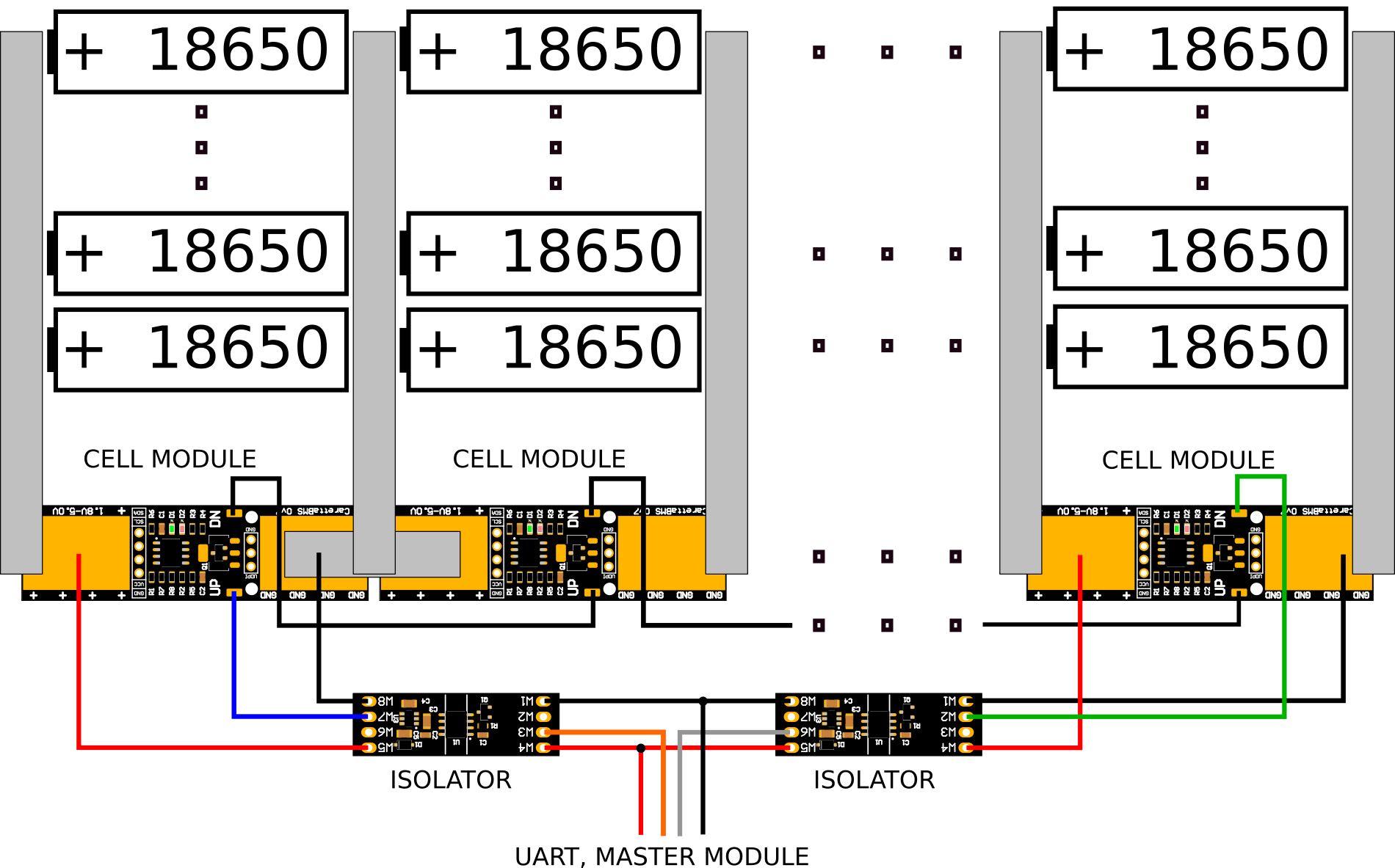
And here are some BMS specs:
- Operating voltage range: from 1.8V to 5.0V
- Operating temperature range: from 0°C to 80°C
- Voltage measurement accuracy: ±10mV
- Voltage measurement resolution: at least 3mV
- Temperature measurement accuracy: ±5°C
- PCB size: 65mm × 18mm × 5mm (same as 18650 cell)
- Pasive cell balancing current: up to 1A
- load characteristics: R = 3.6Ω, Pmax = 4W
- Maximum of series connected cells: up to 256
- Temperature sensors: at least 3 sensors per module (1 internal, 2 external) or up to 32 I2C sensors
- Communication interface (cell modules with master): isolated UART 8E2 (documented protocol)
- Bootloader for future infield firmware upgrades
This project is still work in progress. Right now I am working on the project documentation. I am looking for some feedback and any feature requests.
More about the system is available here: https://github.com/Hrastovc/CarettaBMS
And here are some BMS specs:
- Operating voltage range: from 1.8V to 5.0V
- Operating temperature range: from 0°C to 80°C
- Voltage measurement accuracy: ±10mV
- Voltage measurement resolution: at least 3mV
- Temperature measurement accuracy: ±5°C
- PCB size: 65mm × 18mm × 5mm (same as 18650 cell)
- Pasive cell balancing current: up to 1A
- load characteristics: R = 3.6Ω, Pmax = 4W
- Maximum of series connected cells: up to 256
- Temperature sensors: at least 3 sensors per module (1 internal, 2 external) or up to 32 I2C sensors
- Communication interface (cell modules with master): isolated UART 8E2 (documented protocol)
- Bootloader for future infield firmware upgrades
This project is still work in progress. Right now I am working on the project documentation. I am looking for some feedback and any feature requests.