
You are using an out of date browser. It may not display this or other websites correctly.
You should upgrade or use an alternative browser.
You should upgrade or use an alternative browser.
Boxxbike Valkyrie : 12kw crank concentric mid drive with left hand motor drive
- Thread starter efMX Trials Electric Freeride
- Start date
scrambler
10 kW
I am clearly missing something here.
12S => 44.4V (@3.7V per cell)
12P => 240Amps at 20Amps per cell
Total is 44.4V x 240 Amps = 10.7kW (each cell drawing 20Amps)
16S => 59.2V (@3.7V per cell)
9P = 180Ampx (@ same 20Amps per cell)
Total is 59.2V x 180 Amps = 10.7kW (each cell drawing 20 Amps).
In both case, same power, and same strain on the cell.
MadRhino
100 GW
The reason is that Ohm law says: Impedance does add in a series, and divides in parallel. The longer series using the same number of cells will make a battery that has higher impedance, thus lower C-rate, thus will produce more heat supplying the same watts. The logic of battery performance is that raising the voltage does require more cells, or better ones.
Power is not the issue.scrambler said:I am clearly missing something here.
12S => 44.4V (@3.7V per cell)
12P => 240Amps at 20Amps per cell
Total is 44.4V x 240 Amps = 10.7kW (each cell drawing 20Amps)
16S => 59.2V (@3.7V per cell)
9P = 180Ampx (@ same 20Amps per cell)
Total is 59.2V x 180 Amps = 10.7kW (each cell drawing 20 Amps).
In both case, same power, and same strain on the cell.
At low RPM voltage is irrelevant, need for high torque requires high amps. Cells are drawn upon, do not draw.
The same high amps draw from the motor puts a much higher C-rate load on the lower-Ah layout.
sn0wchyld
100 kW
scrambler said:I was looking at the battery specifications on the BoxxBike, and I was wondering if battery experts care to comment on why they may have chosen the 12S-12P (144cells) configuration, rather than a 16S-9P (also 144 cells) configuration.
The Sony VTC6 cells they use have specs that vary depending where you look but are along the following:
• Volt: 3.6 – 3.7
• Ah: 3.12 – 3
• Max continuous Amp: 15 – 20 – 30
• Peak: 30 – 35
So the 12S-12P means a 43 – 44 Volts battery with a 36 – 37 Ah for a total capacity of about 1,600Wh
Depending what actual cells they used it could provide a Max Continuous power around 7.8kW (@15A), 10.7kW (@20A) or 15.6kW (@30A)
I have usually heard that for more power, using higher Voltage was usually better, yet they are using a 12S ( 43V), rather than 16S (58V) configuration.
I am wondering what makes the 12S a better battery choice for the bike?
i think the 12s is due to the regulations for batteries over 50V... which in EU (afaik) is far more arduous because its the threshold for 'dangerous'... and at 14kw peak, dealing with the thicker wires from the battery is easier than dealing with the extra regs for 50+V systems. Doesn't make a difference to the motor so no real loss overall other than a smidge more copper weight.
But... got the bike this week
As to your other questions
Candice sensor isn't bad, and its got a ramp to the power so its ok, but the switch they were using to cut it out under breaks was apparently unreliable so they've removed it on the latest batch of bikes, much to my chagrin (didn't let me know beforehand). its good for a candace sensor, but still a candace sensor. also means no cut out / clutch for the moto modes, but honestly there I think its a liability, I hated that feature on the surron, as it was hard to know what % throttle you were at when releasing the breaks, and it was like dropping the clutch at some unknown rpm.
few other niggles:
Q factor is quite big, around 300mm, and wider than the quoted 240. Should be able to help this a bit if i can find some 'straight' cranks that dont have the usual 'toe out' offset. combined with the relatively short stock cranks it makes pedaling a little weird. Not awful but not as nice to pedal as a 'typical' bike.
Bike is very tall, geometry more like a moto. im 6'1 and have the seat at its lowest possible height, and id still like it a bit lower if I could, though its not too bad now. will see how it goes but may end up chopping a bit of the seat stem.
Seating position too is a bit too far forward relative to the pedals. An inch backwards would be better, but not a huge problem.
The controller software has some bugs/nuances that they're still working on. Only one to affect me so far is that the motor/controller remains powered for a few seconds after turning everything off... so twisting the throttle can still make things move. Fine if you know its there, but if you didn't the bike could go flying with an accidental throttle twist.
Handlebars sit at around the height of my elbow, standing next to the bike, so quite high also. Feels pretty good on road though so not an issue for me.
For the cutout issue I'm going to chat to the guys about adding it in for the pedal modes, I have some MT5E's so getting a reliable switch is taken care of. I also kind of want a 2 stage switch so very hard pulls on the breaks do cutout the motor in all modes... not essential but a good 'oh shit' option if it can be added.
For the pedals, if anyone knows of some 'striaght' square tapers please let me know. Or if you know how to make your own square tapers I can give that a go.
For the seat, going to see how it goes for now and invest in a slightly lower profile seat stem that should gain another 10-20mm over stock. My discomfort here is likely as much due to coming from my old norko aline and a stealth fighter, both which ride quite low, so could just take some getting used to.
As to the bike otherwise, im pretty happy/impressed so far. been in the 8kw mode most of the time, as I am better suited to thumb throttles and the height and the 220Nm at 12kw makes for a wheely machiene.
:thumb:
feels faster than a stock surron, despite the peak thrust being similar (220Nm vs 200 for the surron, but with a smaller wheel) it puts out that thrust for longer/to a higher speed.
:thumb:
Bike is built like a brick shithouse, feels very solid, much more so than the surron (and defiantly more than the stealth). Feels like I could throw it around far more agressively before things start failing. Having the separate drive lines is a good backup too.
:thumb:
Control on the sixillion is nice, im no fan of full twist but Im finding it pretty controllable. The Magura throttle may be helping that too... They were happy to send me a spare throttle cable connector so I can switch to thumb and give that a go.
:thumb:
Chain noise isn't too bad either. Its there, but its not offensive. Quieter than the surron. I might look to convert to a belt drive, given you can still pedal should the belt go, for some real silent running, but not urgent.
sn0wchyld
100 kW
MadRhino said:The reason is that Ohm law says: Impedance does add in a series, and divides in parallel. The longer series using the same number of cells will make a battery that has higher impedance, thus lower C-rate, thus will produce more heat supplying the same watts. The logic of battery performance is that raising the voltage does require more cells, or better ones.
john61ct said:Power is not the issue.scrambler said:I am clearly missing something here.
12S => 44.4V (@3.7V per cell)
12P => 240Amps at 20Amps per cell
Total is 44.4V x 240 Amps = 10.7kW (each cell drawing 20Amps)
16S => 59.2V (@3.7V per cell)
9P = 180Ampx (@ same 20Amps per cell)
Total is 59.2V x 180 Amps = 10.7kW (each cell drawing 20 Amps).
In both case, same power, and same strain on the cell.
At low RPM voltage is irrelevant, need for high torque requires high amps. Cells are drawn upon, do not draw.
The same high amps draw from the motor puts a much higher C-rate load on the lower-Ah layout.
Im not sure your looking at this right mate...
pack voltage (for the same internal architecture) is largely irrelevant as far as 'strain on cell for given power output'. Much like the winding of a motor has no real impact on its ability to produce torque (the whole 'high torque' vs 'high speed' winding debate from a few years ago), same goes for a battery pack. Each cell, and its interconnects, have a given amount of resistance. That resistance is the same whether arranged in series or parallel, thus the load on each cell, the internal heat generated and the 'wear' or stress they experience for a given power output remains the same.
Take the most simple case... 2s 1p vs 1s 2p. To keep maths simple, lets say each cell is 2V. So a 4V or a 2V pack. If we want 16W, we need to pull 4A from the 2s pack, and 8a from the 1s pack. Each cell however still provides... 4A each.
Each cell has its own + and - side connector, each which adds a set resistance. The 2s pack has 4 of these 'resistors' in series, one from controller to the base of cell 1, 2 between cell 1 and cell 2, and another from cell 2 to controller. The 1s pack has 4 of these arranged in 2 parallel groups of 2. Half the distance, twice the conductor... exactly as per a motor with 1/2x the turn count. So despite drawing 2x the amps... the conductors carrying that 8A are also twice as thick, and half as long. This maintains the same power losses in the I^2R=P equation (R is 1/4 for a 1s pack, offsetting the I^2 with double the current).
Now you'll still need to have larger conductors from the pack to the controller, but a well designed power system should have the controller very close to the +- terminals of the battery, so its often pretty minor compared to the system as a whole. The surron is a poor example of this, given the connection point for the pack could have been closer to its base (or at its base) resulting in a small distance between it and the controller. That 'poor' design choice however can still be offset by using larger conductors... and given the battery/phase wires of a bike make up a very small % of the overall weight having to have larger conductors (on any pack / controller / motor arrangement) is a minor issue. Most people wont mind a 1-2% increase in weight for convenience.
TLDR
Cell arrangement, much like turn counts on a motor, make no practical difference to the strain on the pack, or the heat generated in the motor. Other design constraints will determine an appropriate pack voltage/motor turn count long before considerations of pack voltage / motor efficiency. In extreme cases it can start to have a small impact on net efficiency, but only at orders of magnitude differences, not so much between 50 and 80V.
scrambler
10 kW
Super happy for you (and for me) that you got your bike. I hope you can be patient with the questions ")
(I numbered them to make it easier to answer :wink: )
1. Can you comment to how long it takes for the assist to kick in. Like if you are stopped on a deep slope going up, how much uphill pedaling do you have to do before the assist kicks in?
I usually ride at 970mm (38” ¼) so that should be fine, but I would have hoped I could use a dropper to go lower in some cases, and that may not be possible then...
3. If you can give us the following numbers, that would be great.
• Ground to top of seat tube
• Length of seat tube
• How much could be cut off at the top
6. By the way, have you tested regen, how strong is it in a descent?
Given the way the swing arm triangle is made, it seems you would need to remove the swingarm/motor axle in order to pass the belt, and I don’t know how involve that is.
Below are a few more questions if you don’t mind answering
7. Can you measure the Wheelbase (distance between front and rear axle)?
8. When you are in pedal assist mode, is the full throttle available?
Some bike allow full throttle priority during Pedal assist, other not (or limited to the PAS level like the LMX64). I like to be able to gun the Throttle in an emergency when in Pedal assist mode, so I can quickly get out of a difficult situation without the need to change mode beforehand.
9. Do you know what controller parameters (if any) can be changed by the user?
10. Given the bike has regen, when you pedal the bike, the rear wheel turns the motor front sprocket.
Can you comment on how much resistance you feel when pedaling with zero pedal assist?
11. Is there a USB connector on the display to connect an external device?
A million thanks in advance if you can find the time to answer, and please keep the feedback coming, I have a decision to make
(I numbered them to make it easier to answer :wink: )
This great news, so even if you are on the max power assist, it won’t kick you in the but when it activates.sn0wchyld said:Candice sensor isn't bad, and its got a ramp to the power so its ok,
1. Can you comment to how long it takes for the assist to kick in. Like if you are stopped on a deep slope going up, how much uphill pedaling do you have to do before the assist kicks in?
2. This is one of my concern too. I got info that says the minimum seat height (Ground to top of saddle) is 930mm (36” 5/8) Can you confirm that number?sn0wchyld said:Bike is very tall, geometry more like a moto. im 6'1 and have the seat at its lowest possible height, and id still like it a bit lower if I could, though its not too bad now. will see how it goes but may end up chopping a bit of the seat stem.
I usually ride at 970mm (38” ¼) so that should be fine, but I would have hoped I could use a dropper to go lower in some cases, and that may not be possible then...
3. If you can give us the following numbers, that would be great.
• Ground to top of seat tube
• Length of seat tube
• How much could be cut off at the top
4. Saddle can be adjusted forward and backward some. So are you saying that even if you shift it all the way back, it still feels too forward?sn0wchyld said:Seating position too is a bit too far forward relative to the pedals. An inch backwards would be better, but not a huge problem.
5. I was told the Handlebar was adjustable from 1050mm (41” 3/8) and 1200mm (47” ¼). May be you can confirm if this is at the stem, or at the grips.sn0wchyld said:Handlebars sit at around the height of my elbow, standing next to the bike, so quite high also. Feels pretty good on road though so not an issue for me.
I understand they have a regen switch on the rear brake. May be that signal could also be used to trigger the cutoff.sn0wchyld said:For the cutout issue I'm going to chat to the guys about adding it in for the pedal modes, I have some MT5E's so getting a reliable switch is taken care of. I also kind of want a 2 stage switch so very hard pulls on the breaks do cutout the motor in all modes... not essential but a good 'oh shit' option if it can be added.
6. By the way, have you tested regen, how strong is it in a descent?
I would also love to see a Belt kit for the bike…sn0wchyld said:Chain noise isn't too bad either. Its there, but its not offensive. Quieter than the surron. I might look to convert to a belt drive, given you can still pedal should the belt go, for some real silent running, but not urgent.
Given the way the swing arm triangle is made, it seems you would need to remove the swingarm/motor axle in order to pass the belt, and I don’t know how involve that is.
Below are a few more questions if you don’t mind answering
7. Can you measure the Wheelbase (distance between front and rear axle)?
8. When you are in pedal assist mode, is the full throttle available?
Some bike allow full throttle priority during Pedal assist, other not (or limited to the PAS level like the LMX64). I like to be able to gun the Throttle in an emergency when in Pedal assist mode, so I can quickly get out of a difficult situation without the need to change mode beforehand.
9. Do you know what controller parameters (if any) can be changed by the user?
10. Given the bike has regen, when you pedal the bike, the rear wheel turns the motor front sprocket.
Can you comment on how much resistance you feel when pedaling with zero pedal assist?
11. Is there a USB connector on the display to connect an external device?
A million thanks in advance if you can find the time to answer, and please keep the feedback coming, I have a decision to make
sn0wchyld
100 kW
let me know if you want more precise measurments (all these are like +-10mm, just done quickly before tea)
1. its enough that it'd be a pain on a steep hill if stopped. requires about a 1/4 to half turn of the pedals. seems more responsive once your moving, but that could just be the 'ease' of getting in that first 1/4 odd turn.
2. my saddle right now (to the top of the saddle) is at 950/960. You could probably get lower with a different seat post with a lower profile clamp, but the one it came with... that's as low as she goes, seat clamp bolts (that hold the saddle) are resting on the seat tube. low profile seat would help too.
3.
a. will grab that later, probably about 880 or so
b. about 200
c. about 50 max, though the issue there is that the post is tapered down to fit the seat clamp, the rest of the post is a larger OD. I did mention its built like a brick shithouse yea? so cutting down could be a bit of an ordeal as your 'clamp' is trying to flex thicker material, and you'll have to find a clamp that fits the larger OD of the lower tube section.
4. im as back as far as it'll go without getting weird on the saddle rods. I'm sure there's seat posts that'll gain me another 10mm or so, and seats that'll do the same. Its really not too bad, and if you ride at 970+mm seat height that'll help too as the post is angled back some, and I think if the Q factor could be fixed then it'd also be less of an issue.
5. top of the stem is at about 1070. I haven't measured precicely but I recon you could get it lower than 1050 (its got quite a few spacers and a riser bar, and Id say im at 1150 now, but can measure better tomorrow for you if you want)
6. regen is pretty soft. Will hold speed steady on a very gentle slope but really only an 'engine break' feel. Another point I might ask them about, adding a 2nd throttle for variable regen. Having it on the surron is great, its limited by battery to only 1000w or so but can serve as your only brake outside of steep descents and emergencies (nuk 24F). Having the same here would be great.
7. about 1330mm axle to axle... so quite long. helps keep the front down with all its height, and feels quite stable. Kinda wish the surron was this long, though given how low it is 1250-1300 would be ideal (1200 stock iirc)
8. no throttle. I agree on your points, other than with a twist throttle and accidental use when pedaling hard. might be programmable, I never asked.
9. very few. Display stuff mainly. There is a 'advanced settings' that is behind a code, IDK if they give that out, haven't asked (yet). They did mention you could disable some modes, and I haven't found where so might be behind that code wall.
10. there's some weight, but its not too bad, feels similar to a hub. you wont want to pedal much without the motor, but its ok in granny gears.
11. Not that Ive seen.
another niggle is there is some chain rub too... I can see some slight wear on the lower part of the pedal chain side, rubbing on the frame directly below it, and can feel it a bit when pedalling in the lowest 2 gears. Only just noticed so might just need some adjustment (haven't done much since first ride) but a bit annoying on a expensive bike. On the plus side your not going to be smashing any front rotors, its fully encapsulated by about 5-6mm ally plate... I'm going to work out a way to add a 10mm plate of HDPE as an additional sacrificial bash guard but you wont be hitting anything fragile should you be rolling over stuff. Again... Brick shithouse.
all in all im still pretty happy, just seems theres still some minor bugs/adjustments to work out and get it to 100%. if they can work on making the pedal side of it a bit more ergonomically sound, they'll have one killer bike here, and i think its probably achievable without any major design changes. a torque sensor of some description, a bit more adjustment on the seat height, and a narrower Q factor and its 100%. It aint cheap by any means but still great value compared to the other higher end 'commercial' ebikes.
1. its enough that it'd be a pain on a steep hill if stopped. requires about a 1/4 to half turn of the pedals. seems more responsive once your moving, but that could just be the 'ease' of getting in that first 1/4 odd turn.
2. my saddle right now (to the top of the saddle) is at 950/960. You could probably get lower with a different seat post with a lower profile clamp, but the one it came with... that's as low as she goes, seat clamp bolts (that hold the saddle) are resting on the seat tube. low profile seat would help too.
3.
a. will grab that later, probably about 880 or so
b. about 200
c. about 50 max, though the issue there is that the post is tapered down to fit the seat clamp, the rest of the post is a larger OD. I did mention its built like a brick shithouse yea? so cutting down could be a bit of an ordeal as your 'clamp' is trying to flex thicker material, and you'll have to find a clamp that fits the larger OD of the lower tube section.
4. im as back as far as it'll go without getting weird on the saddle rods. I'm sure there's seat posts that'll gain me another 10mm or so, and seats that'll do the same. Its really not too bad, and if you ride at 970+mm seat height that'll help too as the post is angled back some, and I think if the Q factor could be fixed then it'd also be less of an issue.
5. top of the stem is at about 1070. I haven't measured precicely but I recon you could get it lower than 1050 (its got quite a few spacers and a riser bar, and Id say im at 1150 now, but can measure better tomorrow for you if you want)
6. regen is pretty soft. Will hold speed steady on a very gentle slope but really only an 'engine break' feel. Another point I might ask them about, adding a 2nd throttle for variable regen. Having it on the surron is great, its limited by battery to only 1000w or so but can serve as your only brake outside of steep descents and emergencies (nuk 24F). Having the same here would be great.
7. about 1330mm axle to axle... so quite long. helps keep the front down with all its height, and feels quite stable. Kinda wish the surron was this long, though given how low it is 1250-1300 would be ideal (1200 stock iirc)
8. no throttle. I agree on your points, other than with a twist throttle and accidental use when pedaling hard. might be programmable, I never asked.
9. very few. Display stuff mainly. There is a 'advanced settings' that is behind a code, IDK if they give that out, haven't asked (yet). They did mention you could disable some modes, and I haven't found where so might be behind that code wall.
10. there's some weight, but its not too bad, feels similar to a hub. you wont want to pedal much without the motor, but its ok in granny gears.
11. Not that Ive seen.
another niggle is there is some chain rub too... I can see some slight wear on the lower part of the pedal chain side, rubbing on the frame directly below it, and can feel it a bit when pedalling in the lowest 2 gears. Only just noticed so might just need some adjustment (haven't done much since first ride) but a bit annoying on a expensive bike. On the plus side your not going to be smashing any front rotors, its fully encapsulated by about 5-6mm ally plate... I'm going to work out a way to add a 10mm plate of HDPE as an additional sacrificial bash guard but you wont be hitting anything fragile should you be rolling over stuff. Again... Brick shithouse
. all in all im still pretty happy, just seems theres still some minor bugs/adjustments to work out and get it to 100%. if they can work on making the pedal side of it a bit more ergonomically sound, they'll have one killer bike here, and i think its probably achievable without any major design changes. a torque sensor of some description, a bit more adjustment on the seat height, and a narrower Q factor and its 100%. It aint cheap by any means but still great value compared to the other higher end 'commercial' ebikes.
scrambler said:Super happy for you (and for me) that you got your bike. I hope you can be patient with the questions
(I numbered them to make it easier to answer :wink: )
This great news, so even if you are on the max power assist, it won’t kick you in the but when it activates.sn0wchyld said:Candice sensor isn't bad, and its got a ramp to the power so its ok,
1. Can you comment to how long it takes for the assist to kick in. Like if you are stopped on a deep slope going up, how much uphill pedaling do you have to do before the assist kicks in?
2. This is one of my concern too. I got info that says the minimum seat height (Ground to top of saddle) is 930mm (36” 5/8) Can you confirm that number?sn0wchyld said:Bike is very tall, geometry more like a moto. im 6'1 and have the seat at its lowest possible height, and id still like it a bit lower if I could, though its not too bad now. will see how it goes but may end up chopping a bit of the seat stem.
I usually ride at 970mm (38” ¼) so that should be fine, but I would have hoped I could use a dropper to go lower in some cases, and that may not be possible then...
3. If you can give us the following numbers, that would be great.
• Ground to top of seat tube
• Length of seat tube
• How much could be cut off at the top
4. Saddle can be adjusted forward and backward some. So are you saying that even if you shift it all the way back, it still feels too forward?sn0wchyld said:Seating position too is a bit too far forward relative to the pedals. An inch backwards would be better, but not a huge problem.
5. I was told the Handlebar was adjustable from 1050mm (41” 3/8) and 1200mm (47” ¼). May be you can confirm if this is at the stem, or at the grips.sn0wchyld said:Handlebars sit at around the height of my elbow, standing next to the bike, so quite high also. Feels pretty good on road though so not an issue for me.
I understand they have a regen switch on the rear brake. May be that signal could also be used to trigger the cutoff.sn0wchyld said:For the cutout issue I'm going to chat to the guys about adding it in for the pedal modes, I have some MT5E's so getting a reliable switch is taken care of. I also kind of want a 2 stage switch so very hard pulls on the breaks do cutout the motor in all modes... not essential but a good 'oh shit' option if it can be added.
6. By the way, have you tested regen, how strong is it in a descent?
I would also love to see a Belt kit for the bike…sn0wchyld said:Chain noise isn't too bad either. Its there, but its not offensive. Quieter than the surron. I might look to convert to a belt drive, given you can still pedal should the belt go, for some real silent running, but not urgent.
Given the way the swing arm triangle is made, it seems you would need to remove the swingarm/motor axle in order to pass the belt, and I don’t know how involve that is.
Below are a few more questions if you don’t mind answering
7. Can you measure the Wheelbase (distance between front and rear axle)?
8. When you are in pedal assist mode, is the full throttle available?
Some bike allow full throttle priority during Pedal assist, other not (or limited to the PAS level like the LMX64). I like to be able to gun the Throttle in an emergency when in Pedal assist mode, so I can quickly get out of a difficult situation without the need to change mode beforehand.
9. Do you know what controller parameters (if any) can be changed by the user?
10. Given the bike has regen, when you pedal the bike, the rear wheel turns the motor front sprocket.
Can you comment on how much resistance you feel when pedaling with zero pedal assist?
11. Is there a USB connector on the display to connect an external device?
A million thanks in advance if you can find the time to answer, and please keep the feedback coming, I have a decision to make
scrambler
10 kW
Thanks a lot for keeping up with me!
I agree that for me the one thing that would make the bike the perfect hybrid between a light motorcyle and an EMTB you can actually pedal would be to add a Torque sensor. You should mention it to them, as the more people do, the more chances they would consider it.
Good suggestion on a variable regen...
Definitely push them to change the programming to allow full throttle during PAS, or add another mode where it would be possible.
If you can confirm the precise Wheelbase, that will help me scale the bike picture precisely in a CAD program, and then I can extract all other dimensions from the bike. While at it, if you can also measure the distance between the ground and the top of the small horizontal tube between the seat tube and the downtube (the min stepover height), that would be great.
About the Rub on the pedal chain, I did notice it looked really close in the picture...
This is actually a design thing that bothers me a bit, and it is the fact that you cannot use anything bigger than their 34T sprocket. This is not a problem with a derailleur and chain, but If I was to replace the derailleur by an IGH like Kindernay, I could not also put a Gates belt on that side, because the smallest rear belt sprocket is 22T, and that would require a 55T or 60T in the front for a good high speed pedaling cadence.... (you cant have it all ...)
About the cranks / Qfactor, I found the following that may help.
I found this site with Cranks with variable Qfactor all the way down to zero.
https://mirandabikeparts.com/upload/files/Q-factors.png?1554290576838
Their Q:0 is 27.1mm from inside mount surface to outside pedal mount surface.
If you can check what is the In/Out offset of the ones you have, we can see how much there would be to gain.
The other thing to check is what type of Square taper they used (JIS, ISO, JIS Low profile)
https://www.sheldonbrown.com/bbtaper.html
Assuming Boxxbike uses the JIS one, on the site above the Delta models exist with a JIS taper and their Q:0 offset of 27.1mm, and in various length, including 152mm like I believe the Boxxbike uses.
https://mirandabikeparts.com/en/shop/e-bike/delta
I agree that for me the one thing that would make the bike the perfect hybrid between a light motorcyle and an EMTB you can actually pedal would be to add a Torque sensor. You should mention it to them, as the more people do, the more chances they would consider it.
Good suggestion on a variable regen...
Definitely push them to change the programming to allow full throttle during PAS, or add another mode where it would be possible.
If you can confirm the precise Wheelbase, that will help me scale the bike picture precisely in a CAD program, and then I can extract all other dimensions from the bike. While at it, if you can also measure the distance between the ground and the top of the small horizontal tube between the seat tube and the downtube (the min stepover height), that would be great.
About the Rub on the pedal chain, I did notice it looked really close in the picture...
This is actually a design thing that bothers me a bit, and it is the fact that you cannot use anything bigger than their 34T sprocket. This is not a problem with a derailleur and chain, but If I was to replace the derailleur by an IGH like Kindernay, I could not also put a Gates belt on that side, because the smallest rear belt sprocket is 22T, and that would require a 55T or 60T in the front for a good high speed pedaling cadence.... (you cant have it all
...)About the cranks / Qfactor, I found the following that may help.
I found this site with Cranks with variable Qfactor all the way down to zero.
https://mirandabikeparts.com/upload/files/Q-factors.png?1554290576838
Their Q:0 is 27.1mm from inside mount surface to outside pedal mount surface.
If you can check what is the In/Out offset of the ones you have, we can see how much there would be to gain.
The other thing to check is what type of Square taper they used (JIS, ISO, JIS Low profile)
https://www.sheldonbrown.com/bbtaper.html
Assuming Boxxbike uses the JIS one, on the site above the Delta models exist with a JIS taper and their Q:0 offset of 27.1mm, and in various length, including 152mm like I believe the Boxxbike uses.
https://mirandabikeparts.com/en/shop/e-bike/delta
MadRhino
100 GW
Cells arrangement does make a difference in the pack internal resistance:sn0wchyld said:MadRhino said:The reason is that Ohm law says: Impedance does add in a series, and divides in parallel. The longer series using the same number of cells will make a battery that has higher impedance, thus lower C-rate, thus will produce more heat supplying the same watts. The logic of battery performance is that raising the voltage does require more cells, or better ones.john61ct said:Power is not the issue.scrambler said:I am clearly missing something here.
12S => 44.4V (@3.7V per cell)
12P => 240Amps at 20Amps per cell
Total is 44.4V x 240 Amps = 10.7kW (each cell drawing 20Amps)
16S => 59.2V (@3.7V per cell)
9P = 180Ampx (@ same 20Amps per cell)
Total is 59.2V x 180 Amps = 10.7kW (each cell drawing 20 Amps).
In both case, same power, and same strain on the cell.
At low RPM voltage is irrelevant, need for high torque requires high amps. Cells are drawn upon, do not draw.
The same high amps draw from the motor puts a much higher C-rate load on the lower-Ah layout.
Im not sure your looking at this right mate...
pack voltage (for the same internal architecture) is largely irrelevant as far as 'strain on cell for given power output'. Much like the winding of a motor has no real impact on its ability to produce torque (the whole 'high torque' vs 'high speed' winding debate from a few years ago), same goes for a battery pack. Each cell, and its interconnects, have a given amount of resistance. That resistance is the same whether arranged in series or parallel, thus the load on each cell, the internal heat generated and the 'wear' or stress they experience for a given power output remains the same.
Take the most simple case... 2s 1p vs 1s 2p. To keep maths simple, lets say each cell is 2V. So a 4V or a 2V pack. If we want 16W, we need to pull 4A from the 2s pack, and 8a from the 1s pack. Each cell however still provides... 4A each.
Each cell has its own + and - side connector, each which adds a set resistance. The 2s pack has 4 of these 'resistors' in series, one from controller to the base of cell 1, 2 between cell 1 and cell 2, and another from cell 2 to controller. The 1s pack has 4 of these arranged in 2 parallel groups of 2. Half the distance, twice the conductor... exactly as per a motor with 1/2x the turn count. So despite drawing 2x the amps... the conductors carrying that 8A are also twice as thick, and half as long. This maintains the same power losses in the I^2R=P equation (R is 1/4 for a 1s pack, offsetting the I^2 with double the current).
...
TLDR
Cell arrangement, much like turn counts on a motor, make no practical difference to the strain on the pack...
12 cells in a series, each having 12 milliohm internal resistance, does make a pack with 144 mΩ if it is 1p, 72 mΩ if it is 2p... 12 mΩ for 12p, making the same IR for the pack as a single cell
Now let’s arrange the 12s 12p (12 mΩ pack) into 16s 9p:
16 x 12mΩ = 192mΩ / 9 = 21.33mΩ pack IR
Resistance is not related to current, it is power resistance. So, whatever 1000 watts are from 100 v 10A or 10v 100A, those 1000 watts will suffer the same loss when passing through the same resistance. That is why the 12s 12p battery will have lower loss, running cooler than the same number of cells arranged as 16s 9p when supplying the same watts output.
scrambler
10 kW
MadRhino said:Cells arrangement does make a difference in the pack internal resistance:
12 cells in a series, each having 12 milliohm internal resistance, does make a pack with 144 mΩ if it is 1p, 72 mΩ if it is 2p... 12 mΩ for 12p, making the same IR for the pack as a single cell
Now let’s arrange the 12s 12p (12 mΩ pack) into 16s 9p:
16 x 12mΩ = 192mΩ / 9 = 21.33mΩ pack IR
Resistance is not related to current, it is power resistance. So, whatever 1000 watts are from 100 v 10A or 10v 100A, those 1000 watts will suffer the same loss when passing through the same resistance. That is why the 12s 12p battery will have lower loss, running cooler than the same number of cells arranged as 16s 9p when supplying the same watts output.
OK, good info.
Now the power loss by internal resistance is given by the formula R x I square.
So in a 12S - 12P pack at 20A discharge per cell that is 240Amps if the pack has 12 mΩ internal resistance, the power loss is:
0.012 x 240 x 240 = 691
In a 16S - 9P pack still at 20A discharge per cell that is 180Amps. If the Pack has a 21.33mΩ, the power loss is:
0.02133 x 180 x 180 = 691
Am I still missing something (just trying to educate myself here
)MadRhino
100 GW
the power dissipated from the battery IR is the product of current AND voltage: P = I × V
Your calculations based on Amps only, are giving equal losses because you didn’t account for the voltage differences between the 2 batteries.
Your calculations based on Amps only, are giving equal losses because you didn’t account for the voltage differences between the 2 batteries.
sn0wchyld
100 kW
MadRhino said:Cells arrangement does make a difference in the pack internal resistance:sn0wchyld said:MadRhino said:The reason is that Ohm law says: Impedance does add in a series, and divides in parallel. The longer series using the same number of cells will make a battery that has higher impedance, thus lower C-rate, thus will produce more heat supplying the same watts. The logic of battery performance is that raising the voltage does require more cells, or better ones.john61ct said:Power is not the issue.scrambler said:I am clearly missing something here.
12S => 44.4V (@3.7V per cell)
12P => 240Amps at 20Amps per cell
Total is 44.4V x 240 Amps = 10.7kW (each cell drawing 20Amps)
16S => 59.2V (@3.7V per cell)
9P = 180Ampx (@ same 20Amps per cell)
Total is 59.2V x 180 Amps = 10.7kW (each cell drawing 20 Amps).
In both case, same power, and same strain on the cell.
At low RPM voltage is irrelevant, need for high torque requires high amps. Cells are drawn upon, do not draw.
The same high amps draw from the motor puts a much higher C-rate load on the lower-Ah layout.
Im not sure your looking at this right mate...
pack voltage (for the same internal architecture) is largely irrelevant as far as 'strain on cell for given power output'. Much like the winding of a motor has no real impact on its ability to produce torque (the whole 'high torque' vs 'high speed' winding debate from a few years ago), same goes for a battery pack. Each cell, and its interconnects, have a given amount of resistance. That resistance is the same whether arranged in series or parallel, thus the load on each cell, the internal heat generated and the 'wear' or stress they experience for a given power output remains the same.
Take the most simple case... 2s 1p vs 1s 2p. To keep maths simple, lets say each cell is 2V. So a 4V or a 2V pack. If we want 16W, we need to pull 4A from the 2s pack, and 8a from the 1s pack. Each cell however still provides... 4A each.
Each cell has its own + and - side connector, each which adds a set resistance. The 2s pack has 4 of these 'resistors' in series, one from controller to the base of cell 1, 2 between cell 1 and cell 2, and another from cell 2 to controller. The 1s pack has 4 of these arranged in 2 parallel groups of 2. Half the distance, twice the conductor... exactly as per a motor with 1/2x the turn count. So despite drawing 2x the amps... the conductors carrying that 8A are also twice as thick, and half as long. This maintains the same power losses in the I^2R=P equation (R is 1/4 for a 1s pack, offsetting the I^2 with double the current).
...
TLDR
Cell arrangement, much like turn counts on a motor, make no practical difference to the strain on the pack...
12 cells in a series, each having 12 milliohm internal resistance, does make a pack with 144 mΩ if it is 1p, 72 mΩ if it is 2p... 12 mΩ for 12p, making the same IR for the pack as a single cell
Now let’s arrange the 12s 12p (12 mΩ pack) into 16s 9p:
16 x 12mΩ = 192mΩ / 9 = 21.33mΩ pack IR
Resistance is not related to current, it is power resistance. So, whatever 1000 watts are from 100 v 10A or 10v 100A, those 1000 watts will suffer the same loss when passing through the same resistance. That is why the 12s 12p battery will have lower loss, running cooler than the same number of cells arranged as 16s 9p when supplying the same watts output.
again, your half way there.
I am not for one moment suggesting a high series pack (for the same total cell count) does not have a higher resistance. Im pointing out that despite the higher resistance, the current drawn will be reduced proportionally such that the losses will be... drum roll... the same.
to use your example...
our 16s pack at 21.33 mohm, providing 1000w will require a amp draw of 31A, using the same 2v cells I mentioned earlier.
total losses in pack are 31^2 x 0.0213 = 20W, because losses in a resistor are given by I x I x R = P, or I^2R=P
Lets rearrange this pack to be all in series, since that 'should be' worse efficiency right? the pack does have higher overall resistance, after all...
16 x 9 = 144 cells, or a 288v pack (same 2V cells). 144 x 12mohm = 1.72 ohms
1000W/288V = 3.47A.
3.47A^2 x 1.72ohms = drum roll please..... 20W.
change it for a 1 s 144p pack... we now need 500A draw (1000W/2V), but our pack IR is now 0.083mohm (0.012ohms/144 resistors in parallel).
again, 500^2 x 0.000083 = 20W.
Literally a ratio in pack voltage (and current draw) of 144:1, and 0 difference in the internal losses of said pack.
As I said before, the connection from this crazy 144p pack would need to handle 500A rather than 3.5A in our 144s 288V pack, but the internal losses of this pack are the same as if they were 144s, or anything in between (including 16s, 9p).
just to be clear again...
I completely agree the series - parallel make up of a pack affects its net internal resistance of the pack as a whole. but losses are calculated with a combination of 2 formulas... v=ir and p=vi. No combination of these will allow you to get to a point where, for a given power draw, any particular pack configuration will result in extra power losses within the cell, or it interconnects. This is with the assumption that the interconnects will be the same between a 1s 144p pack and a 144s 1p pack, but that is (broadly) going to be the case IRL, so its a safe assumption.
V=IR, P=VI. All you need mate.
sn0wchyld
100 kW
MadRhino said:the power dissipated from the battery IR is the product of current AND voltage: P = I × V
Your calculations based on Amps only, are giving equal losses because you didn’t account for the voltage differences between the 2 batteries.
Read my last response but put simply, yes and no.
P=IV yes, but for pack IR your using it wrong... you need to use the voltage SAG under load as V, not the pack voltage. so if the pack sags 3.4V under load, and you multiply that by your current draw, bingo... pack losses. the thing is, the pack will sag more in a high series pack, but the current draw will be proportionally lower... so you end up again at the same power losses no matter the arrangement of S and P cells.
sn0wchyld
100 kW
scrambler said:Thanks a lot for keeping up with me!
I agree that for me the one thing that would make the bike the perfect hybrid between a light motorcyle and an EMTB you can actually pedal would be to add a Torque sensor. You should mention it to them, as the more people do, the more chances they would consider it.
Good suggestion on a variable regen...
Definitely push them to change the programming to allow full throttle during PAS, or add another mode where it would be possible.
If you can confirm the precise Wheelbase, that will help me scale the bike picture precisely in a CAD program, and then I can extract all other dimensions from the bike. While at it, if you can also measure the distance between the ground and the top of the small horizontal tube between the seat tube and the downtube (the min stepover height), that would be great.
About the Rub on the pedal chain, I did notice it looked really close in the picture...
This is actually a design thing that bothers me a bit, and it is the fact that you cannot use anything bigger than their 34T sprocket. This is not a problem with a derailleur and chain, but If I was to replace the derailleur by an IGH like Kindernay, I could not also put a Gates belt on that side, because the smallest rear belt sprocket is 22T, and that would require a 55T or 60T in the front for a good high speed pedaling cadence.... (you cant have it all
About the cranks / Qfactor, I found the following that may help.
I found this site with Cranks with variable Qfactor all the way down to zero.
https://mirandabikeparts.com/upload/files/Q-factors.png?1554290576838
Their Q:0 is 27.1mm from inside mount surface to outside pedal mount surface.
If you can check what is the In/Out offset of the ones you have, we can see how much there would be to gain.
The other thing to check is what type of Square taper they used (JIS, ISO, JIS Low profile)
https://www.sheldonbrown.com/bbtaper.html
Assuming Boxxbike uses the JIS one, on the site above the Delta models exist with a JIS taper and their Q:0 offset of 27.1mm, and in various length, including 152mm like I believe the Boxxbike uses.
https://mirandabikeparts.com/en/shop/e-bike/delta
I'll be looking at implementing my own, but yea, will mention it too.
I have no idea re combining modes, but it shouldn't be difficult if the controller can handle the dual inputs (and no reason it cant imo, i doubt its that close to max brain power)
I'll measure the exact wheel base tomorrow. But 1300-1350 is about right if you want some round figures
yep, its a limiting factor but you cant have it all I guess haha. else get a better hub that doesn't requrie the overdrive?
cheers for the links mate, will check them out and find the exact taper. too bad you cant get slightly negative taper, loosing 5mm or so would be damn near perfect and solve all issues in that area
scrambler
10 kW
sn0wchyld said:cheers for the links mate, will check them out and find the exact taper. too bad you cant get slightly negative taper, loosing 5mm or so would be damn near perfect and solve all issues in that area
I doubt they makes negative cranks... for that you could talk to a CNC shop and have them make a custom pair. But you really cant go very far with that or you risk hitting the cranks with your leg.
There may also be a way to reduce Q-factor with shorter pedal spindles.
Keep me posted on a custom Torque sensor, I am happy to help find / design a solution
I have been looking for a way to do that on a bike without a traditional Bottom bracket for a while...
Originally there was one called the BEAMTS that would work on the pedaling chain tension, but they stopped making it.
Below is company that may have or could come up with a usable solution
https://sensitivus.com/products/contactless-torque-sensor-module/
scrambler
10 kW
And if you ever want to do a paint job, I played with different designs for the bike
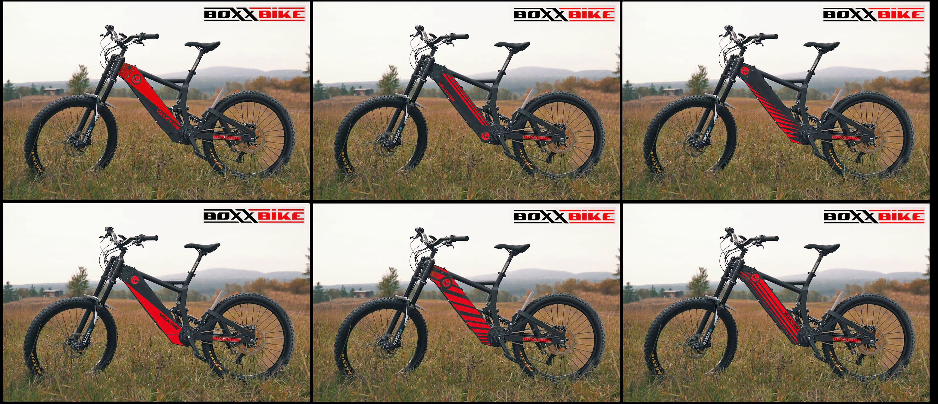
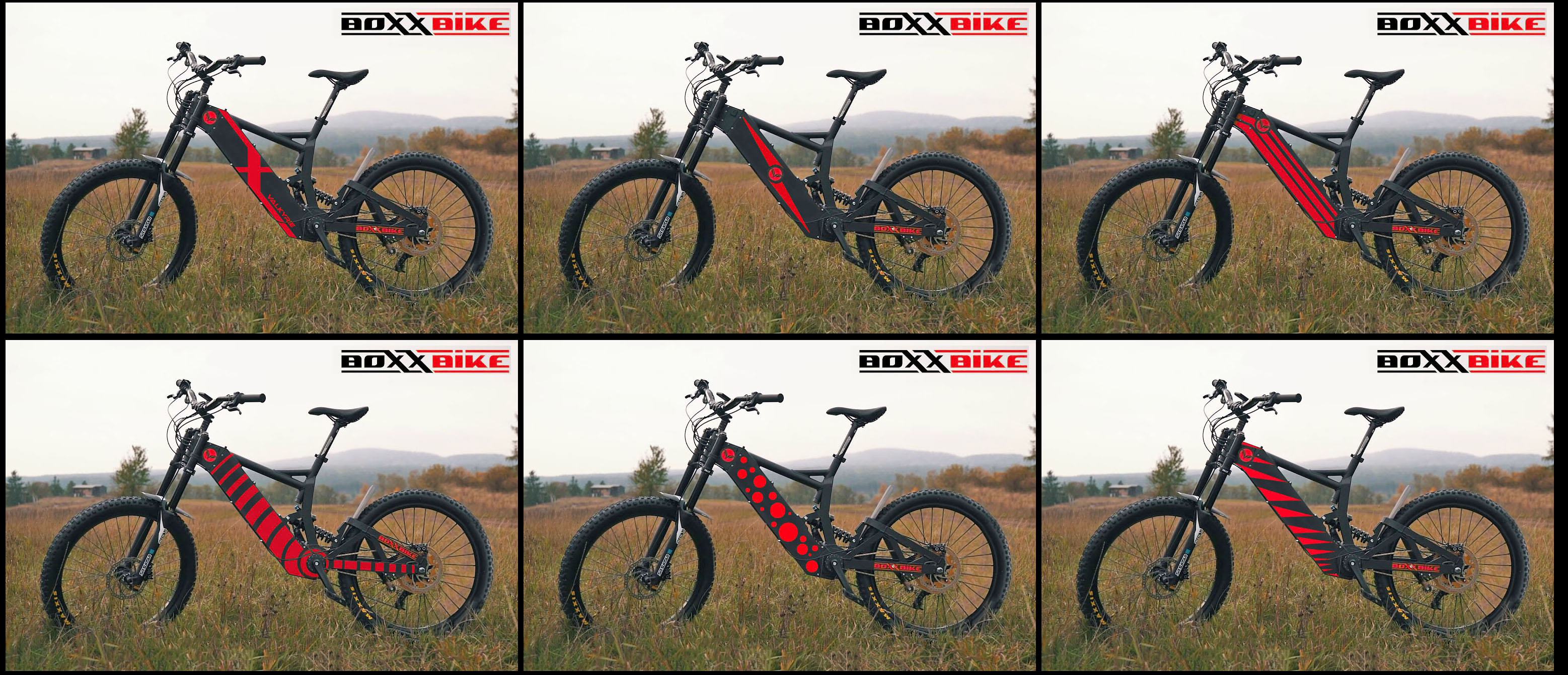
Hi res versions
https://1drv.ms/u/s!At3vMAQjaOZLlE_pin0OEXO2OuJR?e=thkkby
https://1drv.ms/u/s!At3vMAQjaOZLlFDAUwX-ZpGg-ZJl?e=hcqdA8
Hi res versions
https://1drv.ms/u/s!At3vMAQjaOZLlE_pin0OEXO2OuJR?e=thkkby
https://1drv.ms/u/s!At3vMAQjaOZLlFDAUwX-ZpGg-ZJl?e=hcqdA8
sn0wchyld
100 kW
scrambler said:sn0wchyld said:cheers for the links mate, will check them out and find the exact taper. too bad you cant get slightly negative taper, loosing 5mm or so would be damn near perfect and solve all issues in that area
I doubt they makes negative cranks... for that you could talk to a CNC shop and have them make a custom pair. But you really cant go very far with that or you risk hitting the cranks with your leg.
There may also be a way to reduce Q-factor with shorter pedal spindles.
Keep me posted on a custom Torque sensor, I am happy to help find / design a solution
I have been looking for a way to do that on a bike without a traditional Bottom bracket for a while...
Originally there was one called the BEAMTS that would work on the pedaling chain tension, but they stopped making it.
Below is company that may have or could come up with a usable solution
https://sensitivus.com/products/contactless-torque-sensor-module/
Yea i doubt it too, but there's always hope right?
RE torque sensing, i had been thinking of some chain tension measure as its probably the easiest to retro fit and build. main issue I foresee is chain slap/movement over bumps may activate it.
Took the bike for a proper shakedown today, and well, colour me duly impressed. Rode in mode 7 most of the time (about 6kw power limit, ~140Nm at the wheel given the phase amp limit) which was enough given the loose muddy surfaces I was on, any more just made traction difficult. Honestly it feels better than a surron or my 8kw fighter at that level, not quite as much torque low down but still enough to be competitive, at thats at 50% of its max power and 60% of its max torque...
Offroad performance is great, first time i've ever ridden an ebike where I didn't feel the need to baby it or hold back for fear of something breaking, or overheating. This kind of riding would overheat my stealth (mxus v3 with statoraid and hubsinks running at 8kw) in about 5-10 min. The surron too would be getting hotter than the boxx is, though the nuk needs a firmware update as it had a known issue running surron motors... 1+h on the boxx of mixed riding later (500w pedelec stints mixed with exuberant 6-9kw bursts) and the motor casing is barely warm, maybe 30c on a 15c day. No temp on the display but 20min after getting home the casing is at room temp, suggesting the thermal path is quite good (ie was never just poor thermal transfer that kept the casing from getting hot). Motor must be very efficient at these levels, I was doing mainly slow tight hilly single track, where phase amps are high and airflow is low, yet no issues it seems. Managed to get up some reasonably challenging little obstacles, the extra clearance over the surron certainly helps (250mm with a 26 in the front, vs 330).
the pedal sensor is less of a issue than i first thought, torque would still be better but im none the less still happy enough with it. Q factor can be fixed (improved?), as really its only 'just' too wide for my comfort, and I should be able to reduce it by ~30mm with some new cranks. I'd still prefer a lower seat but again, getting used to it now at its ~950 odd mm.
FYI measured the wheelbase again, right on 1330.
Hit me up if you want to know anything else, but to suffice to say i finally have the ebike grin I wanted 10yrs ago haha, but could never maintain because of my breaking and overheating stuff.
Dont mind the diagonal half/half paintjob design, but for me 2 tone grey stickers on black looks shmick. Mine came in gloss black, would have prefered matt/satin but still looks good.
scrambler
10 kW
Thank you for your feedback and for confirming the wheelbase, I can now deduct all the other dimensions.
It is great news to hear the bike does not seem to overheat, and good to know you are finding the Cadence sensor usable.
A chain torque sensor would definitely work, especially because of the concentric Motor and BB. If you feel up to actually build a system from scratch, then have a look at the BEAMTS, it was great in its time and worked on that exact principle.
Below are some of the old Videos from Santa Monica Electric Vehicle
https://www.facebook.com/SantaMonicaEV/videos/an-overview-of-the-beamts-torque-sensor-system/4346230888467/
https://www.facebook.com/SantaMonicaEV/videos/beamts-torque-sensors-are-now-available-at-grintechnologies/1491002760926082/
https://www.facebook.com/SantaMonicaEV/videos/intalling-a-beamts-on-a-prodecotech-bike/1021553321204364/
And below is a thread from someone who installed it on endless sphere (be careful the second link in that thread appears to have malware on it, don't click on it!)
https://endless-sphere.com/forums/viewtopic.php?t=67086
The good thing is that the Silixcon can take both a Cadence sensor input and a Torque sensor input, and do clever programming to blend them for optimal PAS (LMX recently did that on their LMX64 to improve smoothness at sustained pedaling cadence, which is a weakness of a pure torque sensor).
Now regarding that, if you do create a torque sensing solution, you would need Boxxbike to unlock the controller programming. Have you already spoken to them about it, and are they open to that?
I am sure I will have more questions, and I appreciate your willingness to answer.
My ideal Electric bike Hybrid was the Neematic (15kW, pinion gearbox, torque sensing Pedal Assist, 2kWh removable battery....) But that dream vanished when UBCO acquired them and abandoned the pedaling side (and is yet to even release the bike as a light motorcycle...)
Form your feedback so far, it seems the Boxxbike is a worthy alternative.
If you have the opportunity to post close up pictures of the various areas of the bike and especially the handlebar controls, that would be great. And if you ever open the battery box, give us pictures of what things look inside and its inside dimension.
I will try to leave you alone for a while to just enjoy the bike, but please give us additional feedback as you gain more experience with it...
Thanks again for all this!
Grantmac
10 kW
The BEAM TS was definitely a sensor that seemed maybe ahead of it's time. Certainly on dual drive bikes it's a better option than putting the sensor in a wear part like the bottom bracket.
The other approach might be to sense at the rear axle like Stromer does. They use an off the shelf sensor called a TMM4 that mounts in the dropout.
The other approach might be to sense at the rear axle like Stromer does. They use an off the shelf sensor called a TMM4 that mounts in the dropout.
scrambler
10 kW
Shifting the seat back a bit could also be achieved with a setback seatpost
https://www.amazon.com/Setback-Seatpost/s?k=Setback+Seatpost
They can go back up to 40mm, although the more they go back, the less low profile they usually are...
https://www.amazon.com/Setback-Seatpost/s?k=Setback+Seatpost
They can go back up to 40mm, although the more they go back, the less low profile they usually are...
scrambler
10 kW
I like that one, it makes the bike look slimmer
scrambler
10 kW
sn0wchyld said:RE torque sensing, i had been thinking of some chain tension measure as its probably the easiest to retro fit and build. main issue I foresee is chain slap/movement over bumps may activate it.
So I had another look at how we could create a Torque sensor similar to what the BEAMTS use to do, using the Chain Tension as a measure of the pedaling effort (torque applied to BB).
The BEAMTS was the same type of sensor as the TMM which is being used on the rear axle of Stromer or Juiced Bike.
They all use a hall sensor and a magnet mounted on two areas of a steel plate that is cut so that one part can slightly move when there is an effort applied on the Axle. When there is pressure on the axle, one part of the plate moves ever so slightly causing the magnet position in front of the hall sensor to change and produce a variable voltage signal output. The plate movement (and therefore the signal) is proportional to the pedaling effort (torque applied on the BB) and can be used by the controller to modulate the Power assistance based on torque level (pedaling power).
May be we could repurpose one of the TMM like torque sensors which are available as spare parts for the Stromer, the Juiced Bike or the TRANZX bike (see links below).
We would mount a wheel on the part of the Steel plate that normally receives the rear axle, and attach the other part to the frame. We mount it on the frame so the wheel is under the top of the pedaling chain causing a certain amount of up deviation. As the chain tensions, it will apply pressure to the wheel (and therefore the sensor plate) and create a small deformation of the plate in a similar way the rear axle normally does.
Looking at the Boxxbike, I believe there is a good place for such a sensor on the middle part of the swing arm triangle, so I made a 3D mockup of what it could look like. By adjusting the height position of the sensor, we can change the pressure level applied to the wheel, and therefore the amount of deformation it creates in the sensor so it is in the acceptable sensor range.
Note: I modeled it attached to the front of the swing arm as it is easier to visualize, but there is probably space to attach it at the back of the swing arm for a stealthier look.
That said, in a rear dropout situation, the axle is tightened onto the frame dropout and the sensor, in addition to the sensor being attached to the frame, so the amount of movement is reduced. It is possible that if mounted as shown above, the induced movement would be too great for the sensor range. In that case, we could extend the mount plate to also include the Axle (like in the rear frame dropout situation), and hopefully get into proper range.
Note: By changing the mounting angle of the sensor, we can also reduce the amount of deformation induced from the pressure on the wheel, so that gives us a third method to try and match the sensor range with the chain tension/pressure range.
The only way to be sure would be to buy one of these sensors, mount them, connect them to power (usually 5VDC), and measure the voltage on the output pins while putting pressure on the pedals to see If we get a variable reading over the whole range of pedal pressure. If we do, it should be possible to connect the signal output to the controller torque input, and program it to handle the information properly.
I contacted Silixcon and they say they can work with users to finalize programming, but it would require Boxxbike approval for them to do so.
Let me know what you think.
Juiced bike / Stromer TMM sensor: https://www.juicedbikes.com/products/juiced-bikes-current-series-torque-sensor?variant=18177155205
Stromer Sensor output measure: https://www.youtube.com/watch?v=31IxS91QJZY
TranzX sensor: https://hollandbikeshop.com/en-gb/bicycle-parts-electric-bicycle/tranzx-e-bike-parts/tranzx-e-bike-sensor/tranzx-sensor-tmm4-derailleur-speed-short-cable/
Grantmac
10 kW
I think you'd want to keep it as close to the chain wheel as possible to reduce variation cause by which gear you are in.
Mounting the roller under the chain should increase the measurement as you shift to higher gears, mounting it above should do the opposite.
I wonder if that hall sensor itself is an off the shelf item from some other industry?
Mounting the roller under the chain should increase the measurement as you shift to higher gears, mounting it above should do the opposite.
I wonder if that hall sensor itself is an off the shelf item from some other industry?
scrambler
10 kW
Grantmac said:I think you'd want to keep it as close to the chain wheel as possible to reduce variation cause by which gear you are in.
Mounting the roller under the chain should increase the measurement as you shift to higher gears, mounting it above should do the opposite.
You are right, I was thinking of my situation where I would be using an IGH and therefore a single rear sprocket
I will look at a better location/mount for people with a derailleur...
The one I used is the TranzX one which is their own, but you can do the same with the TMM4 used by stromer or juiced bike. You can cut the derailleur part as it is useless and make it more compact.Grantmac said:I wonder if that hall sensor itself is an off the shelf item from some other industry?
If you meant just the Hall sensor component on the whole thing, yes I am sure it is an off the shelf hall sensor.
Similar threads
- Replies
- 15
- Views
- 5,030
- Replies
- 1
- Views
- 270
- Replies
- 25
- Views
- 3,052
- Replies
- 13
- Views
- 1,579
- Replies
- 20
- Views
- 2,053