Open source BMS for 48V to 400V lithium-ion battery pack

User guide link for the interested & also block diagram for SS version:

User guide (work in progress):
https://drive.google.com/file/d/1uOrFBpyzokOVYcjlZ8XJ_fpcNXJhhk6q/view

Block diagram:
https://drive.google.com/file/d/1m466abl468eSJYFaoC2uhdircRuGtzbd/view
 
Updated the website with the smaller “SS-LITE” version for pre-ordering:
https://www.ennoid.me/battery/bms-ss-lite

Also added a few documents at the bottom of the page: Block diagram, Pinout, .step file & dimensions
 
Tested the first final SS-15S unit yesterday on the testbench. It seems to work well so far and passed all initial testing. I even tried to kill one unit by disconnecting balance & power cables in all kind of stupid order while in operation. It still hold well:

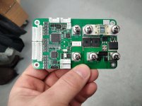
Here a pic of one of the 15 units freshly assembled:
e7ba83c42e879c992c3c7b29dd49a9e7aab90b61.jpeg

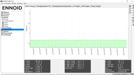
Another pic showing the app connected to the test unit in operation:
44817d8cbf1ab4bf1975425c4e4a116f713e146c_2_1035x582.png

Please note that SOC is showing 100% despite cell voltages being at approx. 2.7V. This is normal due to the brand new BMS. SOC will get reset after a full charge and will start counting properly from there. There is also a few mV mismatch between cell graph & cell data show at the bottom, but this is due to the small differences between subsequent measurements done by the BMS and by the fact that the bench test is actually a resistor array powered by a varying DC power supply.
 
dont you use a internal voltage reference to mitigage erronious readings due to junk on the incoming voltages?

when does the bms classify the battery as "fully charged"? when it reaches the voltage limit (say the CV portion of the charger) or when the current actually has dropped to a certain value?
 
Very technical question, why so?

There are digital filters implemented in the firmware to elimimate spikes or bad data that would normally create an error for voltages or temperature readings.

The IC used for cell voltage measurement (LTC68xx) has sofisticated internal voltage reference system with triple reference validation. On top of that, a separate 16 bit external measurement IC compare pack voltage to the sum of cell voltages.

Two main adjustable parameters will define charging/balancing completed. The charging current is below the defined limit & cell mismatch is below the defined limit while also considering the soft overvoltage defined value, balancing start voltage, pack hysterisis (sag) & related defined timeouts. The default settings are normally good enough, but user can change those values afterward depending of pack caracteristics or personnal preferences.
 
ENNOID said:
Very technical question, why so?
There are digital filters implemented in the firmware to elimimate spikes or bad data that would normally create an error for voltages or temperature readings.
The IC used for cell voltage measurement (LTC68xx) has sofisticated internal voltage reference system with triple reference validation. On top of that, a separate 16 bit external measurement IC compare pack voltage to the sum of cell voltages.
Two main adjustable parameters will define charging/balancing completed. The charging current is below the defined limit & cell mismatch is below the defined limit while also considering the soft overvoltage defined value, balancing start voltage, pack hysterisis (sag) & related defined timeouts. The default settings are normally good enough, but user can change those values afterward depending of pack caracteristics or personnal preferences.

i ask it because stuff like controllers, chargers and other stuff might/will give lots of crap on the power supply of the bms. you dont want anything to upset the actual readings. so if you already get difference in mesurements on the bench it might be something to look at. its those fun little gremlins that can pop up when you start messing around with your actual board. i used to just hook up every frequency generator i had at the same time and let them do random sweeps all over the place to upset the readings.

nice to see some thought into the SoC. some bms that i have used simply use a voltage trigger and nothing else so the battery states its 100% when its barely out of its CC stage causeing a massive difference in real vs stated SoC.

would it be possible to "learn" the voltage curve of a new battery so when the battery ages it can correlate expected SoC with the actual pack voltage and power measured by the shunt and it would result in a extremely accurate SoC display regardless of the chemistry/voltage curve.
it would be an advanced feature but that could give you the difference between a fixed "this was the battery capacity when new" and "this is measured capacity now". it would require something like a "learn" mode and the user/builder would need to connect a load bank to the battery to empty the battery from full to the set LVC for the bms to correctly register the actual capacity and correlate the voltage with the actual SoC. it could then also trigger an alert if the expected voltage does not meet measured readings wich would indicate a worn out battery or some vampire drain form high self discharge for example.

just brainstorming here. the processor in question has a lot of power still left untapped so that would be a nice addition for later as its completly software based.
 
Glad to hear some new ideas. All mentionned is possible.

The more affordable SS version is meant for experimenting those kind of things. Anyone can take the code and bring new advanced features to the actual product. The use of high quality components with good computing power allow fine tuning and advanced features to be implemented. I have a lot on my plate already, so any help is welcome.
 
certainly a solid SoC calculation should be possible. a fairly simple one would be to have 10 voltages you can set manually for 10% icrements of actual SoC the pack builder tested with cells outside the bms. so you can just so a single cell test on the bench by recording voltages at 10% SoC steps and enter those so it can display the proper SoC curve regardless of the measured power passed by the bms. that should give the user a warning if the 2 values (measured SoC by the shunt vs the programmed expected voltage curve) are out too much. especially in cold temperatures for example you see this behaviour very well. tesla does this as well by showing a "missing" piece of the battery SoC when the battery is too cold.
 
Some updates: for the EBMS project

After many charge/discharge cycles @ 70A continuous discharge completed, I feel confident enough for starting the shipment of the 15S version this week. Some bugs were corrected during testing and some new features implemented with the small I2C display (larger fonts, all datas now available & user can shuffle between shown datas with the power push button)

I should receive the 18S boards (SS & SS-LITE) this week and will start testing them.

Next on my to do list:

- Finalise the 24S version and order PCBs for testing
-Make the QT mobile bluetooth app works on android (the QML code seems to work fine on build mobile windows, but I’m struggling with android deploy ABI X86 config stuff…) maybe someone here is a QT specialist and could help…EBMS-tool repo is all on github and available.
-update NRF51 repo for use with EBMS packets ID instead of VESC
-Validate + improve CAN implementation between EBMS & VESC
- Implement throttling (max. allowed current & regen control) into VESC code over CAN bus.
 
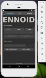
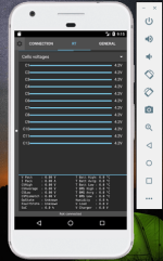
I finally been able to run the QT app on Android:
Untitled.pngUntitled2.png

Goal is to connect an NRF51 Bluetooth module onto the BMS, so user can connect with a phone to change settings & get real time data
 
Looks like 21700 is coming on the scene. eBay lists not only square brackets for the 21700, but also hex brackets. I am going hex.

I think I will move to the Samsung 21700 50E, with either 14s8p or 14s11p modules,depending on the total voltage I need, which I am not sure yet. Since it is 2C, the currents are 80 A and 110 A respectively.

I haven't caught up with your new developments with the BMS yet. But it looks great. I don't mind putting an STM32 and a 3.5" display in each pack. Does the BMS-SS support SPI or I2C?
 
There is an I2C connector which support external display SSD13xx already implemented in the firmware.
Default is using SSD1306 0.96'' display.
Larger SSD1309 2.42'' I2C display also works.

User can switch between displayed data from the main ON/OFF push button with short press. Things like, SOC, pack voltage, pack current, cell voltages, humidity, temperature, charging, balancing etc. can be shown on the display. More options will come related to this quite convenient display in the future firmware updates.

There was not enough space for both I2C & SPI connector on the SS, but pins are available on the MCU. So, it could be possible in theory to offer a BMS version with an SPI connector one day. Honestly, I don't think it is worth it because going with SPI display will require quite a lot of computing power from the MCU to get nice & fast display effects. In that case, it would be better to have a separate MCU dedicated for that. I2C is enough for displaying the basic stuff.
 
i was looking at the shop site and i noticed your "optional" 30cm balance wire set.

30cm is too short. please add a 50~70cm length set if possible from your supplier. there is nothing more annoying then having to add 10~20cm of wire 20 times. the time it takes to do the soldering and heat shrinking is not a fun job. this is partly why i stopped using the tinybms. their wires where too short and making a longer version to i could solder-plug-play and be done in 20 minutes instead of dicking around for 2 hours was "impossible" on their end even if i wanted to buy a couple dozen sets.

if possible you might want to look into sillicone balance wires for better abriasion resistance.
 
Will try to find prebuilt silicon balance wire with JST PH comnector that would fit your needs.

I have been testing many different design of PCB based battery pack with cylindrical cells that eliminates the hazard related to using balance cables. I posted some picture in this thread long time ago showing the idea. Things have evolved since... Almost direct plug & play. Drop the cells in the plastic case, all cells in the same orientation with BMS on the side, balance cables 10cm long board to board, PCB fuse, tidy & clean. All routing & cell connections are done on the top PCB also the main power path going through the PCB. Similar in some aspect to the trampa board battery pack design but with way fewer components. That is mostly why I haven't spent too much time on finding longer balance cables...
 
Nice firmware. I think the SSD1309 2.5" should do the job. Would I have access to the firmware, to patch in my display and rotary encoder code? Also in-pack statistical monitoring I would like to patch.

Actually the 3.5" display is not SPI. It is embedded. But 2.5" would do.

I2C is just fine. The flight computer will use I2C to get the performance data from the pack.
 
OK, I see that this is an open source project. Beautiful. Are the schematics also available?

The current limit in HD type is 150 A and 120 A. That should be adequate for my project.

My modules each have two banks of 14s11p for 5.6 kWh per module. So that is 2s14s11p. It can also be configured 2p14s11p, but I don't plan to do that.

Is there any way to stretch the 18s-24s HD to 28s or 30s? I think you may find many folks doubling the banks but wish to use one BMS. 14s and 13s is pretty much a standard. This will force me to go to 12s per bank.

Let's say I need 32 kWh, which is a pretty low number, but weight is paramount for flight. Thus I would need 6 modules of 2 banks each. I rather have 6 BMS and not 12 BMS.
 
Solarsail said:
Let's say I need 32 kWh, which is a pretty low number, but weight is paramount for flight. Thus I would need 6 modules of 2 banks each. I rather have 6 BMS and not 12 BMS.

do a number 2 before taking off to compensate. :roll: :mrgreen:

or just wait until he releases his 18S and 20S models. :roll:
 
Is there any way to add an isolated CCCV charger on board? A longer board such as 6 x 15 is just fine.

Even a 5 A or 10 A charger on an HD board would be highly desirable. 5 A charging will take 10 hours for a 10p 21700. Which is great for overnight charging.
 
Solarsail said:
Is there any way to add a CCCV charger on board? A longer board such as 6 x 15 is just fine.

Even a 5 A or 10 A charger on an HD board would be highly desirable. 5 A charging will take 10 hours for a 10p 21700. Which is great for overnight charging.

its a bms, not a charger. a charger has no business even being near the bms. your concern is a couple hunderd grams of extra weight in your plane but dont have an issue with adding 5 pounds per pack on individual chargers?

i think it would be better to make your own thread first and ask the basics there.

ps: 1 big charger is lighter and cheaper then a dozen small ones.
 
No offense to you, but I have to agree with flippy. Look for the basics first before asking for nonsense.

Also,

A longer board such as 6 x 15 is just fine.

No, not fine.
 
ENNOID said:
No offense to you, but I have to agree with flippy. Look for the basics first before asking for nonsense.
A longer board such as 6 x 15 is just fine.
No, not fine.
6 x 15 is fine for me and many others. Prove me wrong Ennoid.

Can someone explain Flippy's comment? It sounds nonsense. I understand it is not an easy job to add four more ports to the 24s, but in case you have not manufactured the board yet, then it should still be in the realm of possibility.

While I am in the mode of asking for more features, can you also add a step-up transformation to the charger? 24V to 48V supplies are common. But we need 24 * 4.2 = 101V CCCV. Come on Ennoid, don't tell me it's a bad idea to add a 48 to 101 isolated step-up CCCV trickle charger to the board. It is a terrific business idea. Always keep an open mind and think out of the box.

Not sure why you are offended when someone is very constructively asking for improvements and features.
 
Solarsail said:
It is a terrific business idea.
its not. and please stop using 1980 tacky sales tactics.

Solarsail said:
Always keep an open mind and think out of the box.
pretty sure you need to stay inside the box. you have no concept of the basics, let alone be in a position to ask for crazy features that dont make sense and are only to serve you personally and nobody else.

Solarsail said:
Not sure why you are offended when someone is very constructively asking for improvements and features.
without trying to sound rude: you are not being constructive, you are being ignorant. you have no clue what you are even asking or even have the understanding why it would be a bad idea.

if you want to discuss your situation further you need to start your own topic and ask for help there, not here. this is about the development about this bms, not a place to make a wishlist/demands for your own pet project. if you want to make changes for your individual need: this bms is open source so you can download all the files you need and change it wup, even add a charger if you want. but that stuff does not belong in this thread. you need to make your own. and i highly recommend you do because you need help with understanding the basics. especially if you really want it to fly.
 
flippy said:
Solarsail said:
Is there any way to add a CCCV charger on board? A longer board such as 6 x 15 is just fine.

Even a 5 A or 10 A charger on an HD board would be highly desirable. 5 A charging will take 10 hours for a 10p 21700. Which is great for overnight charging.
its a bms, not a charger. a charger has no business even being near the bms. your concern is a couple hunderd grams of extra weight in your plane but dont have an issue with adding 5 pounds per pack on individual chargers?
I think you are confusing a CCCV charger with a power supply. A 5A trickle CCCV charger can probably be built in under 100 grams. Why is this important? Because you don't want to be hauling 6 or 9 separate isolated charger boxes and all the associated cabling and connections when flying from one location to another location. Or one large charger box containing the same thing: 6 to 9 chargers. How else will you charge 6 or 9 permanently and serially connected modules simultaneously? Where one module's negative is connected to another module's positive?

The BMS is handling currents switched at high frequencies by the inverter and up to 150A. How do you expect a 5A low-frequency isolated switched current that is properly shielded to have an EMF impact?
i think it would be better to make your own thread first and ask the basics there.
Please don't tell me how to behave and how not to behave. In particular after the nonsense of your previous comment. My comment pertains specifically to Ennoid's BMS.
ps: 1 big charger is lighter and cheaper then a dozen small ones.
Only if that were possible. I have 6 to 9 modules permanently cabled together in series. How do I charge the modules with a single charger? By running around every three hours and re-plugging the charger? Or are you suggesting a 900V charger which will not work as you are dealing with multiple BMS in series? I will have to build a power multiplexer with 6 to 9 contactors and a controller and an enclosure and communications. For overnight charging, I will have to charge each module at the rate of 30A to 45A which the BMS cannot handle. At the BMS limit of 20A, my charge time now doubles for the entire pack.

I would like to hear your solution to this problem. Clearly you did not understand the problem.
 
6 x 15 is fine for me and many others. Prove me wrong Ennoid

No need to prove anything.

Just go yourself and visit the E-skateboard forum & you will see all requests that I received from many user about the initial BMS size...it was considered as "huge" or would not fit in most builds even when only 6x14cm...so I decided to swith the SS design to dual sided components & ended up at 6x10cm & 6x6.5 for SS-LITE which is a good improvement IMO.

They even pushed me to go with USB C which I did. They had a point.

The design for SS & SS-LITE 15S & 18 are completed & in production. The 24S version is 90% completed (second iteration), I'm now just trying to fit the whole thing on 6x10cm and testing should start in a month or so...
 
Back
Top