New ground-up ESC - MESC_FOC_ESC

Hi all,

This is an educational post, because I was intrigued. Not the current state of the project.

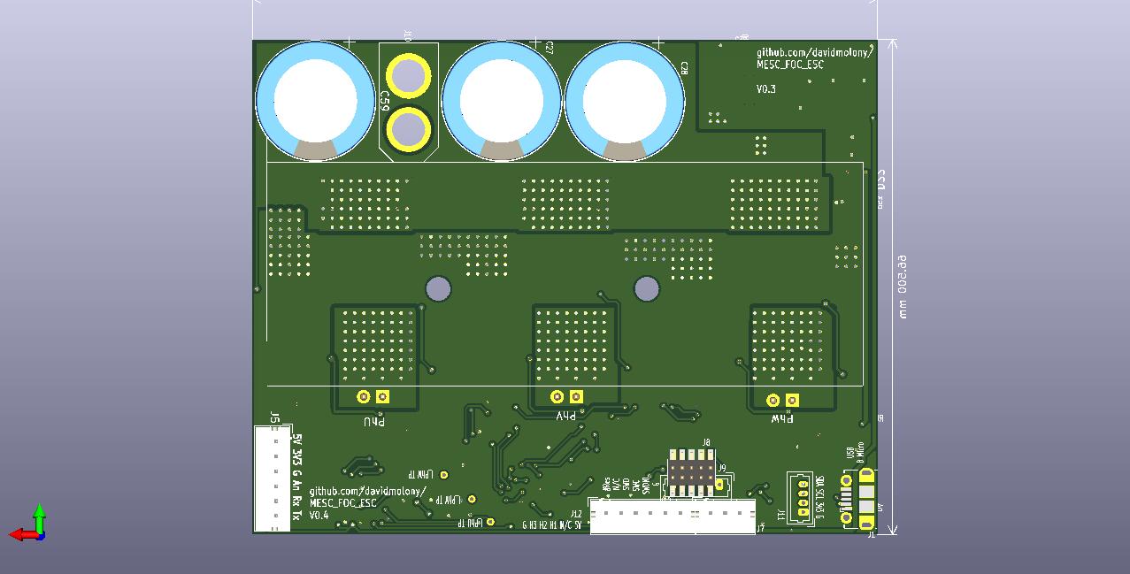
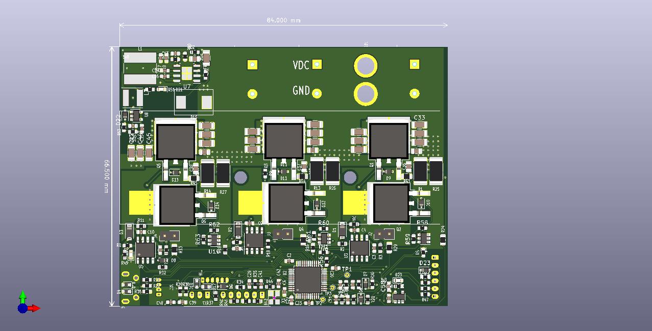
I have a few of the old version boards kicking about with D2pack FETs and snubbers. I wondered what the double pulse test was like for them.

Oh sheeet.....
V1 double pulse test Current 1mohm 16gain.PNG
Current was only up to 40A and voltage at 23V bus. The old version had 2x2mohm shunts paralelled for 1mohm.

V1 double pulse test Rising.PNG
The overshoot is enourmous on the rising edge of the old board!!

V1 double pulse test Falling.PNG
The undershoot is also pretty big on the old board...

V1 double pulse test.PNG
Can't actually remember what the snubbers were, but I do recall they did very little.

This looks a lot worse than it is, because the bus voltage is small, and the current induced overshoot won't scale with voltage, but clearly 18V overshoot and 10V undershoot at 40A is absolutely miles away from the results of the other board.

Perfectly workable actually given the target for the board was originally ~40A continuous, 80A peaks with ~15s (63V) safe, but the progress between this and the latest board is just stunning. A different FET package and a small rearrangement and the capability has more than doubled.

I rode this exact board to work for a few months, it's done hundreds of miles at 13s with no issues. I got 5 almost fully populated boards for like 65GBP (90USD) so the capability was already pretty great.

Regarding the new board:
marcos said:
From the pics I think my board has at least 1/2 the parasitic inductance and stiffer dc link.

The low side shunt, wire bonding inside your fet, the caps arrangement, the stackup, they are all increasing your parasitic inductance. In my board miller is limiting both turn on and turn off swiching speed. In any case, looked acceptable so its running on the dyno now.

I have a few ideas to get further improvement:
1) Remove the dual fit on the D2Pak. I think it's clear now that D2Pak is crappy compared to TOLL. This means I will be able to push everything a bit tighter still.
2) I can't particularly see why the decoupling caps need to be connected to the low side of the shunt. If I went VDC to shunt high, on a few of the ceramic caps at least, the inductive loop need not include the shunts. This might remove a decent portion of the remaining inductance. The difference between 1.5nH and 1.1nH perhaps.
3) Might be able to overlap the shunt high net and the VDC net a bit on an inner layer, which would eliminate some more.

New layout concept.PNG
New layout concept v2.PNG
I really am not sure this is worth the effort though given the previous results. I certainly won't be buying more boards to try it, but if Stancecoke's testing goes well (he's had one on his jig and spun it up...) perhaps there will be another order!
 
Rearranging has begun. This should reduce the inductance a bit more, AND I realised I could reduce the size o the board a bit. It's now 56.5mmx84mm, a full cm smaller compared to the old version.
Also I think this makes for an easier GND layer reinforcement (basically just a bar now...), and a slightly improved VDC plane on the back of the board (bit wider, was probably already plenty enough).
MESC_FOC_ESC_Top View size reduction.png
MESC_FOC_ESC Lower inductance layout.png
Needs a bit of tidying up and the gat signals etc need re-routing, but that's not a biggy.
Marcos, Peters, any comments? I'm not planning on buying/building these. For now. Only do this if people start to actually want them! The current boards are not holding up my development in any way!
 
mxlemming said:
I have a plan. I'm going to artificially bump the switch node voltage with the low side gate unattached, but switch and gate pulled to 0V just prior to the experiment. I should then see the miller capacitance bounce the gate without decaying into the gate driver, so it will be visible after all transients are over. The only decay will be due to scope and gate leakage. If necessary i can buffer the gate with an opamp (got some lmc6484 kicking about from years ago... 20fA leakage current).

This will verify the input to Miller capacitance ratio, and if i do it at a few voltage levels I'll be able to replicate the miller capacitance vs voltage curve. Any excess over this jump when used in double pulse/motoring is therefore inductive/artifact.

Hopefully we can then close this down for good with a complete understanding.

I did this. Results below, I think this is now cleared up, closed etc...
First, I lifted the gate resistor, so the MOSFET is no longer being driven by the gate driver. It's impedance is several Mohms.
Gate resistor lifted.PNG

I then induced an artificial break state (all FETs off) and then used a wire to jump the VDC to the switch node, thus causing a step change from 0V to VDC on the Vds of the low side MOSFET. The resistors for measuring phase voltage (82kohm) keep it pulled to ground normally.

I monitored the gate-source voltage for a number of different Vds steps - below is the 46V response.
48Vds step gate bounce.PNG

The highest I could get with my lab PSUs (not keep on doing this with Lipos) is 69V. I zoomed right in on this one. You can see there are two phenomena - the miller gate bounce, and a short lived inductive artifact.
69Vds gate bounce, zoomed.PNG

Looking at the IPT015N10 datasheet, we can see the Crss drops at higher Vds. Thus we would not expect the miller effect to be linear with voltage.
IPT015N10 capacitances.PNG

I plotted this for Vds steps of 12, 24, 36, 46, 69V:
Miller voltage VS Vds step.PNG

We can see the result is kind of what would be expected from the capacitance chart from Infineon. I have not bothered to numerically integrate the Infineon curve, just... integration by eyeballing.

Further, if we consider the charts in the datasheet for threshold gate voltage, we see that at 140degC and 280uA current flow, the gate threshold is about 2V. The FET doesn't really turn on properly and conduct 10s of amps until about 3V, so even at the 85V intended max working voltage, or 100V Vds breakdown, there will not be a miller turn on.

On another note, this may be a useful technique for Peters et al to test their special high inductance high Crss Fets. I would be very interested to see this repeated for a FET more prone to parasitic turn on and with big ol' through hole legs.

Hope this has been informative/useful for some of you :D

The TLDR is: This is absolutely fine. Move along now, nothing to see here.
 
mxlemming said:
Rearranging has begun. This should reduce the inductance a bit more, AND I realised I could reduce the size o the board a bit. It's now 56.5mmx84mm, a full cm smaller compared to the old version.
Also I think this makes for an easier GND layer reinforcement (basically just a bar now...), and a slightly improved VDC plane on the back of the board (bit wider, was probably already plenty enough).
MESC_FOC_ESC_Top View size reduction.png
MESC_FOC_ESC Lower inductance layout.png
Needs a bit of tidying up and the gat signals etc need re-routing, but that's not a biggy.
Marcos, Peters, any comments? I'm not planning on buying/building these. For now. Only do this if people start to actually want them! The current boards are not holding up my development in any way!
I can only guess, the loop is smaller, but is there space between the FETs for shielding or overlapping layers? I don't know which is better: a small loop without shielding or a slightly bigger loop with shielding.

mxlemming said:
On another note, this may be a useful technique for Peters et al to test their special high inductance high Crss Fets. I would be very interested to see this repeated for a FET more prone to parasitic turn on and with big ol' through hole legs.

Hope this has been informative/useful for some of you :D
Yes it's useful. Maybe I'll try but now my circuit is assembled and mounted to heatsink, but basically this is what the lower value Rgoff and/or the miller clamp is used for.
 
Hi mxlemming, awesome work and thanks for sharing. What kind of stackup did you use? copper weights and number of layers etc. I'm developing a lower power board for desktop experiments (hope to share once it has some maturity) but to keep the cost down I'm using 2-layer 3 oz.--without the extra layers for power routing it's super ugly.
 
I'm curious to see how well it performs thermally. I've worked with some power SO8 devices in SMPS designs and found thermal management to be challenging when using a PCB as a heat transfer medium. I could only manage about 5W of waste heat produced mostly by 2x SO8's on a 45x45mm board area with a 40x40x10mm heat sink stuck to the bottom using forced air cooling with 1oz copper, top/bottom 0.5oz inner.

I suspect you would achieve higher power with more spacing between the devices. Scope shots already look good, modifying to lower inductance further appears unwarranted unless your doing it as an academic pursuit.

Nice work!
 
everythingisawave said:
Hi mxlemming, awesome work and thanks for sharing. What kind of stackup did you use? copper weights and number of layers etc. I'm developing a lower power board for desktop experiments (hope to share once it has some maturity) but to keep the cost down I'm using 2-layer 3 oz.--without the extra layers for power routing it's super ugly.

Currently 4 layer: 1oz .5oz .5oz 1oz

The design migrates very well to 2layer. I started 2 layer and have kept the routing so that it's easy to return to 2 layer.

However, my strong advice from my findings is to save money on copper weight and spend money on layers. Route the power externally and make it easy to add lumps of copper in key places. Doing it this way, you can keep the nasty MOSFET killing artifacts much smaller and run them closer to their voltage limits, just by reducing the parasitics. This means... Lower voltage lower Rds on parts etc.

If you look at the git repo from back last autumn you can find 2layer commits.

zombiess said:
I'm curious to see how well it performs thermally. I've worked with some power SO8 devices in SMPS designs and found thermal management to be challenging when using a PCB as a heat transfer medium. I could only manage about 5W of waste heat produced mostly by 2x SO8's on a 45x45mm board area with a 40x40x10mm heat sink stuck to the bottom using forced air cooling with 1oz copper, top/bottom 0.5oz inner.

I suspect you would achieve higher power with more spacing between the devices. Scope shots already look good, modifying to lower inductance further appears unwarranted unless your doing it as an academic pursuit.

Nice work!

Thanks, in fact a big thanks to everyone here who's helped out, it's been great. Sorry if I've been curt at any point :lol: I've had a vision, a direction and have stuck to it, cherry picking the advice. There's been really great advice, and things I've willfully ignored despite being tried and tested beaten track.

Thermal testing will be the next big thing. I have a bit more time now and more funds since starting a new job, so I'm going to have a crack at building up a dyno soon. For now, all I can say is that the board remains basically cool while the 80mm can motor on my ebike gets rather hot with no heatsink atall.

Edit:
I suspect you're right about the spacing. Thinking back, I knew ages ago i could rearrange and make it smaller but didn't because i was keeping the copper area for heat transfer larger. I might delete this branch of development, or leave it to go stale in case someone else is interested.

I plan on trying a version where i punch an 8mm plated through hole under the FETs, then popping an 8mm copper disc in there. That'll get the conduction as good as to220 to the heatsink. Surprised this isn't common place already.
 
Outside of power stage design :

I spent an hour this morning to look at the MESC design & schematics. I just realized that there was no CAN interface. I think this could become an issue for some users. I know modifying the pinout design to enable CAN would require a lot of work, but I'm still wondering if...

Quick question: Maybe it could be possible to re-organize the MCU pinout to allow a CAN interface? I see that PB8/HALL3 & PB9/SCA are in the way of CAN pins. Reorganizing some pins by moving HALL inputs to timer 3, PWmin to Timer 4 & moving SDA to another SDA_I2C1 enabled pin would work I think. See below the quick changes I made that would free up the CAN pins.
Untitled2.png


The only thing missing with my quick drawing is an additional ADC input for BoardTemp, but some I2C device do exists for temperature sensing.
 
CAN is not something I'd realised anyone actually used.

The problem with the layout you've generated is that I need three consecutive pins for my hall sensor code (I'm not actually using the timer to get the hall commutations and while I made it like this for exactly the intention of using the timer, the PLL type mechanism I've developed seems plenty good for anything I've yet tested). This is not insoluble by a long way, it just eats up more clock cycles.

I'll revisit.
 
mxlemming said:
CAN is not something I'd realised anyone actually used.

If you only run one ESC then you probably have no use for CAN.

CAN is very useful when you have multiple devices and want to control them via a single, robust interface. The VESC CAN interface is not very developed yet, at least not compared to something as mature as the J1939 standards in the automotive world, but it's workable. They are also beginning to implement the open source UAVCAN standard which has a lot of promise.

And I can't leave without saying thanks for a very informative thread. Regarding the layer count "debate" - use as many layers as is practical and stays within your budget. If done properly, 4 layers can be leveraged to yield much lower inductances than 2. That goes for 6 and 8 layers as well but with increased cost. 4 x 2oz layers can get you quite a bit of copper and much better thermal properties than 4 x 1oz for not a lot more cost. Going 3oz and up used to be heavy copper and really jacked up the cost, but depending on where you source boards from it seems like 4oz is the new threshold. Note that you need to use wider trace width and spacing rules for heavier copper. The pin pitch on certain components will dictate the minimum trace/space requirements which will dictate how much copper you can use on the outer layers.
 
mxlemming said:
I plan on trying a version where i punch an 8mm plated through hole under the FETs, then popping an 8mm copper disc in there. That'll get the conduction as good as to220 to the heatsink. Surprised this isn't common place already.
It's called "copper inlay", I'm also wondering how it would perform compared to a bunch of vias.
 
peters said:
mxlemming said:
I plan on trying a version where i punch an 8mm plated through hole under the FETs, then popping an 8mm copper disc in there. That'll get the conduction as good as to220 to the heatsink. Surprised this isn't common place already.
It's called "copper inlay", I'm also wondering how it would perform compared to a bunch of vias.

I did the math a while ago. The copper inlay absolutely crushes vias for performance. It makes the PCB thickness virtually irrelevant.

Thanks for naming it. Now i know what to search for it seems there are a few suppliers... Jlcpcb isn't one of them.

bww129 said:
mxlemming said:
CAN is not something I'd realised anyone actually used.

If you only run one ESC then you probably have no use for CAN.

CAN is very useful when you have multiple devices and want to control them via a single, robust interface. The VESC CAN interface is not very developed yet, at least not compared to something as mature as the J1939 standards in the automotive world, but it's workable. They are also beginning to implement the open source UAVCAN standard which has a lot of promise.

And I can't leave without saying thanks for a very informative thread.

Thanks.

Problem is, I don't have time to actually develop a vesc like eco system. I'd kind of like to, but I'd need a few reasonably competent programmers in tow.
 
bww129 said:
mxlemming said:
CAN is not something I'd realised anyone actually used.

If you only run one ESC then you probably have no use for CAN.

CAN is very useful when you have multiple devices and want to control them via a single, robust interface. The VESC CAN interface is not very developed yet, at least not compared to something as mature as the J1939 standards in the automotive world, but it's workable. They are also beginning to implement the open source UAVCAN standard which has a lot of promise.

ENNOID said:
Outside of power stage design :

I spent an hour this morning to look at the MESC design & schematics. I just realized that there was no CAN interface. I think this could become an issue for some users. I know modifying the pinout design to enable CAN would require a lot of work, but I'm still wondering if...

Following your comments i spent half an hour this lunchtime and came up with the following:
f303 pinout.PNG
Moving the hall to timer 3 and 1 gpio works fine and frees up CAN. At low speed the timer isn't really useful and at high speed it's actually easier and better to have it running off just 1 hall sensor. Presently I'm not even using the timer, but I definitely want encoder capability.

Everything else remains the same.

So it can have everything. Next PCB rev I'll do this.

I'm not going to be coding CAN interfaces any time soon though, if people are off the opinion this project is worth progressing more rapidly, has substantial value and can help with it, make yourself known. I'm not adverse to adding people to the project to make code changes etc.

I'm going to have a big step on the code soon, that is, it'll get ported to f405RG hardware with the correct pinout to run on typical VESC hardware. I've done some of the work already, saying up pwm and ADC readings, and have a few sample vesc hardwares available. Since there's vast numbers of VESC based hardware already out there, this code should become readily usable by tens, hundreds off thousands... of people.

Compared to VESC code, I think it's better to keep this simple and more ebike like, focusing on raw FOC/motor drive performance with bare minimum support to make it legal on an ebike with common inputs.
 
It never hurts to include support for it in your design. If you don't want to use CAN then just don't populate the CAN transceiver and supporting components. Unless you're really cramped for space there's not much downside.

The company I work for has just become interested in a modular BLDC motor controller with a CAN interface so everything on a machine can be controlled via a central CPU on the CAN bus. I am trying to persuade them to let me design a VESC variant so we can improve the CAN implementation, potentially more along the J1939 standards. One other thing we'd like to add is a CAN bootloader so you can do software updates in the field via CAN instead of USB. Not sure how all this will pan out, but I'm sure we're not the only company that wants to use CAN as the main communication bus on a machine.
 
bww129 said:
It never hurts to include support for it in your design. If you don't want to use CAN then just don't populate the CAN transceiver and supporting components. Unless you're really cramped for space there's not much downside.

The company I work for has just become interested in a modular BLDC motor controller with a CAN interface so everything on a machine can be controlled via a central CPU on the CAN bus. I am trying to persuade them to let me design a VESC variant so we can improve the CAN implementation, potentially more along the J1939 standards. One other thing we'd like to add is a CAN bootloader so you can do software updates in the field via CAN instead of USB. Not sure how all this will pan out, but I'm sure we're not the only company that wants to use CAN as the main communication bus on a machine.

Consider the licencing conditions of VESC code if you're using it commercially... It's probably not acceptable. Most companies will shun gpl licenses really hard, since it can force them to release vast amounts of valuable proprietary code base for the inclusion of small portions of code.
 
Yes, they know it is open source and that code additions would be open source. Adding a CAN bootloader, while not trivial, would likely be based on the existing ST CAN bootloader which isn't proprietary. Changing the CAN messaging format to be more J1939 like is a different story. The open source UAVCAN might be a better direction in that regard.
 
One thing to note about the ST CAN bootloader is that they specify the use of PB13 CAN2_TX pin 34 and PB5 CAN2_RX pin57 on the STM32F405 as the bootloader pins. This differs from PB8 CAN_RX pin 61 and PB9 CAN1_TX pin 62 used on the VESC. I'm not much of a software guy and don't know if those can be reassigned or if they are HW specific for the bootloader functionality.
 
bww129 said:
One thing to note about the ST CAN bootloader is that they specify the use of PB13 CAN2_TX pin 34 and PB5 CAN2_RX pin57 on the STM32F405 as the bootloader pins. This differs from PB8 CAN_RX pin 61 and PB9 CAN1_TX pin 62 used on the VESC. I'm not much of a software guy and don't know if those can be reassigned or if they are HW specific for the bootloader functionality.

They're hardware specific and relate to the built in bootloader that comes factory installed/as part of the hardware. It's intended for in circuit programming.

You could use the other CAN, but you'd have to implement your own bootloader protocol. Or find one off the shelf.
 
Moving the hall to timer 3 and 1 gpio works fine and frees up CAN. At low speed the timer isn't really useful and at high speed it's actually easier and better to have it running off just 1 hall sensor. Presently I'm not even using the timer, but I definitely want encoder capability.

Thank you for enabling CAN on the hardware side, I might be interested to help later this year on firmware dev, once I get over my BMS stuff. I'm not sure to understand exactly how you have done it, so the PWM input is now identified as GPIO and no more hall3 input? I was not even aware of using only one hall would work, but I found this and yep : https://www.ti.com/lit/an/slaa695/slaa695.pdf?ts=1617292617540&ref_url=https%253A%252F%252Fwww.google.com%252F...
 
Sorry, to clarify, there are 3 hall inputs... 2 with timer3 inputs and one gpio. My code uses pwm cycle counting for the hall sensor to angle timings combined with a phase locked loop. It works pretty well at all ebike speeds but with high kv motors it struggles since the number of pwm cycles per hall sector becomes rather low.

The rcpwm in gets stacked on top of the swo line on timer 2 channel. Swo is optional, not yet really figured out what makes it so great tbh.

Single hall doesn't work well for startup. In fact i don't think it works atall unless you are using analog halls and an adc channel. At high speeds, single hall becomes preferable since the jitter is proportionally lower and there's no placement irregularity to deal with.


The downside of doing this conversion is that it probably won't be compatible with the ST FOC library any more. I can't really understand why ST decided this combination of pins to functions was a good choice but hey. The ST FOC library is not exactly stable and easy to use.

ENNOID said:
Thank you for enabling CAN on the hardware side, I might be interested to help later this year on firmware dev, once I get over my BMS stuff. I'm not sure to understand exactly how you have done it, so the PWM input is now identified as GPIO and no more hall3 input? I was not even aware of using only one hall would work, but I found this and yep : https://www.ti.com/lit/an/slaa695/slaa695.pdf?ts=1617292617540&ref_url=https%253A%252F%252Fwww.google.com%252F...
 
mxlemming said:
V0.4%20board%20bottom.jpg


V0.4%20board%20top.jpg


Massive board rearrangement since Zombies noticing that the board resistance is probably an issue. Board is now a different shape - 84*66.5mm(5586mm2), instead of 100*50. This is a ~12% area increase which is annoying but oh well. Should allow for a big old lump of copper on the top to pass the ground current between shunts and ground pin, and hopefully better analogue readings as a result. VDC subject to less current, and have observed the current PCB doesn't get too hot riding Ebike around with ~60 phase amps, so that is on the bottom, with no intention of needing any reinforcement.

Added INA181, because, quite simply it appears that the onboard opamps of the F303 are not fit for purpose. After wondering for ages why current readings are randomly offset from each other at zero current, soldering huge jumper wires to the boards, observing the current being different on each of 3 phases post opamp, I have concluded that external 13 cent opamps are a worthwhile investment, and will aid portability to the F4/H7/L4/XMC4100/whatever. Should maintain compatibility with internal opamps as well as external ones.

I've also been playing around with the Infineon XMC FOC libraries, and am rather impressed. Seriously easy to set up, and the sensorless control is really good. I made a board with little TO-252 FETs a year ago, and frankly the layout was crap, but it just works beautifully. The downside compared to STM is that it's a more involved ecosystem to get into, and the peripherals are way harder to get your head around, but they actually seem to be better, more flexible. The other downside is no onboard hardware overcurrent/voltage protection, and it is not effectively implemented in software, so I have burnt a few FETs, whereas the ST libraries and my control algorithm seem broadly utterly immune. Probably easy enough to implement as a few lines in the ADC interrupt, but that's for another day.

On the MESC firmware side, I've been riding the Ebike around with it, and it is definitely not as good as the VESC yet, but not a million miles off. Main difference is noise, and slightly slower (probably due to lack of over modulation ability).

Wish I had more time and energy to spend on this. Still only getting 5 or 6 hours a week :(

Hey mxlemming, I just noticed you tried XMC a year ago. I used XMC4500 for a couple of projects requiring quick and dirty control, without too much high performance and I was equally impressed. The code generation and setup capabilities are really nice, even if the documentation is a bit sparse. Definitely would recommend this for anyone who understands the theory and wants to roll their own code without worrying about register settings and startup code.
 
Something general for all that home brewed controller projects:
How should the various interrupts be prioritized? With a very fast processor, this might not that important, but there should be higher and lower priorities in principle.

My idea for the order:
1. Hall sensor interrupt for rotor position.
2. phase current reading callback + Clark/Park and inverse
3. UART, CAN, SPI, whatever communication

The PI control for id and iq has not to be done in an interrupt, as it is not time critical in the rotating frame.

Any other suggestions?!

regards
stancecoke
 
stancecoke said:
Something general for all that home brewed controller projects:
How should the various interrupts be prioritized? With a very fast processor, this might not that important, but there should be higher and lower priorities in principle.

My idea for the order:
1. Hall sensor interrupt for rotor position.
2. phase current reading callback + Clark/Park and inverse
3. UART, CAN, SPI, whatever communication

The PI control for id and iq has not to be done in an interrupt, as it is not time critical in the rotating frame.

Any other suggestions?!

regards
stancecoke

Generally agreed, but... The PI controls actually take very little computation though. St and Infineon libraries both include them in the fast loop interrupt. I think you're right, they don't need to be.

Tracking the rotor position and updating the pwm accordingly is most important, if you lose track, everything crashes within a few pwm cycles. You could probably last a few seconds without updating the current control unless your motor physically gets jammed.

Phase current reading is very important 1) because you can deal very rapidly with over current and over voltage events. 2) because it enables the feedback for current control.

Current control probably only needs doing on the time scale of mechanical change in speed... 100hz would be fine. Probably. But it's needs doing regularly.

Coms etc only need doing fast enough to provide user response perception. They need doing otherwise how do you stop it...

My scheme is to run:
ADC (triggered by pwm timer) interrupt, highest priority
1) current checks
2) clark and park
3) hall/angle update (not using a timer or seperate interrupts for this)
4) FOC PI
5) inverse park and clark
6) write pwm

Timer 3 pwm input capture interrupt for rcpwm
Uart input interrupt
Both low priority

If i was running on a less capable processor (I wouldn't for a diy job, the f303 isn't any more cost than the f103, and blesses you with an fpu and 72MHz...)
ADC triggered my pwm timer interrupt:
1) check levels are safe
2) update the angle position
3) Inverse park and clark/svpwm
4) Write pwm

Hall change interrupt: this occurs less frequently than pwm, so can run between pwm/adc interrupts. Where possible, a reset mode timer should be used for best accuracy of the hall change timing irrespective of the interrupt priority.
1) Recalculate position/PLL
2) Recalculate per cycle step

FOC PI on a once every 10ms basis, timer rtos, while 1 or otherwise...

Comms ad hoc when not busy.

Where possible I'd offload comms etc to dma
 
There's probably many ways to do this. My original intention was to periodically generate the next 50 or so pwm periods and have the dma throw them in on a cycle by cycle basis. But I couldn't be bothered with that and never ran out of clock cycles at 35khz so...

If running centre aligned pwm it could be advantageous to update the pwm twice per period, once at underflow once at overflow.

If you've got phase current sensors you could probably just run it completely asynchronously, as fast as while 1 allows.

But why bother? The mcu costs less than a single one of my MOSFETs, so it only makes sense to optimise if there's off the shelf hardware that has crap firmware...

Different story if you're talking about a 9euro f405. But if you're strapping it to a 1000$ bike out board then I guess there's a similar argument.
 
Thank you for your assessment!

As you know, I'm using commercial China hardware, so I have to take the processor and the pinout "as is".

Some users report "misfires", audible random ticking or clicking while the motor is running.
I can't really reproduce this. So one idea is, there are sometimes problems with the order of the interrupts...

Actually I read in the halls by GPIO_EXTIx. The motor hall signal is on PA0, PA1 and PA2, so I could use Timer2 input capture channel 1,2 +3 also. I can not assess whether this makes a big difference

regards
stancecoke
 
Back
Top