
You are using an out of date browser. It may not display this or other websites correctly.
You should upgrade or use an alternative browser.
You should upgrade or use an alternative browser.
TSDZ2 mid drive with 860C, 850C or SW102 displays only -- Flexible OpenSource firmware (Casainho code only)
- Thread starter casainho
- Start date
electroriderIT
10 mW
- Joined
- Aug 31, 2020
- Messages
- 27
GUYS...lately
I write this that may be helpful to some of us!
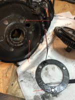
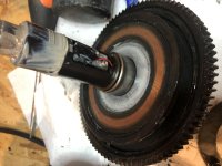
I Had some issue ( never had one with Casainho super releases)...when the motor gets warm I feel I have to push more on the pedals to obtain the same response. to solve this ( temporarily) I stop the bike and give a downward kick on the pedal...that must "move" something...and all the torque comes back.... so despite at first I though was the firmware (but checked everything and its completely fine)...I understood from that ....that it was a hardware problem...probably the 3 little springs where locked or not free to move, so when I kick they come back where they should ...So today I opened the motor and maybe I found the problem.....but want to ask to the ones of you that have more experience.This is the situation , see pics ( already a little bit cleaned!):
maybe during the last service I made one year ago..I put way too much grease...and it went completely on the spings area and sensor.
What do you think? grease may compromise sping movement, making it less responsive.
HOW do I prevent grease from going in that area...I just lubricated the big gear from outside...so..some gasket maybe doesn't work properly?
Ley me know what you think of my deductions.... I will clean an test the motor as soon as I can ( what to mount temperature sensor and temperature pads also )
Ciao guys!
I write this that may be helpful to some of us!
I Had some issue ( never had one with Casainho super releases)...when the motor gets warm I feel I have to push more on the pedals to obtain the same response. to solve this ( temporarily) I stop the bike and give a downward kick on the pedal...that must "move" something...and all the torque comes back.... so despite at first I though was the firmware (but checked everything and its completely fine)...I understood from that ....that it was a hardware problem...probably the 3 little springs where locked or not free to move, so when I kick they come back where they should ...So today I opened the motor and maybe I found the problem.....but want to ask to the ones of you that have more experience.This is the situation , see pics ( already a little bit cleaned!):
maybe during the last service I made one year ago..I put way too much grease...and it went completely on the spings area and sensor.
What do you think? grease may compromise sping movement, making it less responsive.
HOW do I prevent grease from going in that area...I just lubricated the big gear from outside...so..some gasket maybe doesn't work properly?
Ley me know what you think of my deductions.... I will clean an test the motor as soon as I can ( what to mount temperature sensor and temperature pads also )
Ciao guys!
Attachments
Haschi1989
10 µW
- Joined
- Dec 24, 2020
- Messages
- 6
Hello I m using at the moment the SW102 display. But it is hard to read under direct sunlight. Is the 850 better?
Is it possible to use the 500C display with OSF ?
Other question will the "new" 850 displays for tsdz2 work with OSF.
Regards
Is it possible to use the 500C display with OSF ?
Other question will the "new" 850 displays for tsdz2 work with OSF.
Regards
Mr.Flibble
10 W
- Joined
- May 5, 2020
- Messages
- 90
Haschi1989 said:Hello I m using at the moment the SW102 display. But it is hard to read under direct sunlight. Is the 850 better?
Is it possible to use the 500C display with OSF ?
Other question will the "new" 850 displays for tsdz2 work with OSF.
Regards
I don't know if this helps, but the 860c is great in sunlight.
a11yhacker
100 µW
I'm trying to connect my TSDZ2 (coaster brake version) with the 860C. The motor has a 6-pin female connector, and the display has a 5-pin female connector. I really don't want to cut open any of the original connectors on either device, at least until I am 100% happy with my configuration.
It looks like what I need is a cable similar to the 5- to 6-pin conversion display harness from Eco Cycles, but they are out of stock and told me that they may not ever restock that item. So I plan to make a 5-pin male to 6-pin male cable.
I have gathered a few of these connectors via some extension cables, but I'm not certain about the pinout, especially on the display side. The wiki page shows the pinout on the motor side, and the pinout on the 8-pin cable, but not for the 5-pin. There's a table there that instructs how to connect the 6-pin and 5-pin by wire color, but since I don't want to open the cable I don't know what the wire colors are, and I don't trust the extension cables I'm cutting open to get the wire colors right.
I've seen a few pinouts for the 5-pin Bafang connector, such as the one on this post. Before I started wiring things together I wanted to double check that this pinout should match my TSDZ2 and 860C. Can anyone confirm and/or point to some reliable documentation for these cables?
Haschi1989
10 µW
- Joined
- Dec 24, 2020
- Messages
- 6
Hello community,
after switching over to the 860C and using a matt screen protector, I could see all information on the screen under direct sunlight.
Thank you all for this advise and the good manual.
Today I had to replace the blue gear. After completing the work I want to go on a testride. I turned the display on and waited. On the screen was the advise "keep pedal free...." but it dosen't disappears. I thought ok, maybe I cut a cable. So I opened the left side of the housing and everything was fine. I plugged the charger in and waited. Nothing still the same situation.
Now I can imagine that the controller software is erased. Is this possible? Did someone has a similar problem before?
I'm using a 36V 250W motor with OSF 1.1.0
regards
A bit easier to find with a linkSemogonif said:See the post by: perryscope » on Aug 05 2020 3:04pm
")
https://endless-sphere.com/forums/viewtopic.php?f=30&t=93818&start=6045#p1575672
imho this couldn't be the case after a gear revision.Haschi1989 said:..... replace the blue gear. ........ On the screen was the advise "keep pedal free...." but it dosen't disappears. ....
.... controller software is erased. Is this possible? ....
Such a message indicates that a sensor is sending a wrong message to the controller, so that the engine is not ready to start.
To replace the blue gear you have to disconnect some of the cables and connectors, so it seems to me that something went wrong there.
Elinx said:A bit easier to find with a linkSemogonif said:See the post by: perryscope » on Aug 05 2020 3:04pm
https://endless-sphere.com/forums/viewtopic.php?f=30&t=93818&start=6045#p1575672
How to properly use the OS-ebike firmware and TSDZ2 controller v1 on another motor?
I burned three pairs of power transistors under similar circumstances...
1) 18s2p lifepo4 I was driving fast on a sandy dirt road and suddenly there was no traction. Knocked out three capacitors, two mosfets and a protective diode in the display sw102
2) I Replaced the controller. I rode on the gas stick, jumped off the curb, the wheel spun in flight, after landing everything went out. Knocked out the largest capacitor 63V and a pair of power transistors
3) 15s3p fully charged, 50V. I replaced the capacitors with 100 volts, replaced both power transistors. I ran over the curb and pedaled, knocked out the same transistors.
.jpg")


.jpg")

Please, help!
I burned three pairs of power transistors under similar circumstances...
1) 18s2p lifepo4 I was driving fast on a sandy dirt road and suddenly there was no traction. Knocked out three capacitors, two mosfets and a protective diode in the display sw102
2) I Replaced the controller. I rode on the gas stick, jumped off the curb, the wheel spun in flight, after landing everything went out. Knocked out the largest capacitor 63V and a pair of power transistors
3) 15s3p fully charged, 50V. I replaced the capacitors with 100 volts, replaced both power transistors. I ran over the curb and pedaled, knocked out the same transistors.
Please, help!
casainho
10 GW
- Joined
- Feb 14, 2011
- Messages
- 6,045
Is great to see someone using the TSDZ2 motor controller, our OpenSource firmware and the wireless controller, on another mid drive motor.livello said:How to properly use the OS-ebike firmware and TSDZ2 controller v1 on another motor?
The issue you are having can be something due to that motor being different - it may have lower resistance and or inductance, and all the controller hardware and also the firmware are not ready for fast current changes on that type of motors.
Still, if you wanna try again, I would recommend to disable the Field Weakening feature. Also lower the motor phase current as also the battery current. Also reduce the current ramp value.
Peacepirate
100 mW
- Joined
- Sep 22, 2020
- Messages
- 40
Hello,
i observed a strange behaviour of the values displayed on the sw102 and wonder whether someone could enlight me.
A few days ago the battery soc was all over sudden always 0% although it reseted to 100% in the past when the voltage was above 54,0v.
Today i checked how to reset the display (fw 0.8.0) and was happy to see that it finally switched to 100% again although i cant estimate whether it will work and decrease or not because i didn't used the motor yet.
The LM35 temp sensor worked fine for months and i believe it showed more or less the correct temp. Today i intended to test how smoothly the motor works and changed in the display settings from temp sensor to throttle.
The motor didnt react to the throttle. Instead the temperature value on the display changed according to the throttle (0 -255).
I checked the voltage on the adc pin and my multimeter displayed values between approx. 0,9v and 3,3v.
Although the minimum voltage of throttle output is 0,9v (LM35 should show something like 90° degrees) the coresponding temperature value was 0 and the displayed temp value started to increase only if the voltage was above 1,5v.
Since i don't use the throttle anyway i switched the display settings back to temp sensor but the value on the displayn still shows 0 now.
I checked the value of the LM35 with my multimeter and it was about 0,30v - sensor seems to be okay because room temp was about 26 degrees.
Walk Assist works and the whole rest of the systems seems to be okay.
My question: Could it be that only the adc pin of the STM8 Chip broke? Is this possible?
Regards
casainho
10 GW
- Joined
- Feb 14, 2011
- Messages
- 6,045
Maybe. It is always good to have new working components to test against.Peacepirate said:My question: Could it be that only the adc pin of the STM8 Chip broke? Is this possible?
I just wrote this message, where I had similar issue on the TSDZ2 wireless controller, because I exchanged the UART TX and RX wires, I had to trash the board and use a new one -- and that took me time to understand!
https://endless-sphere.com/forums/viewtopic.php?p=1668844#p1668844:
casainho said:So, yesterday I took a lot of time to figure out what issues I was having because one TSDZ2 wireless board was not working... turns out I was very tired already and exchanged the UART TX and RX wires. I had to use the oscilloscope to discover that the constant "alive" signal sent by the motor controller was very small and near 5 volts, so, the wires were exchanged. But after, the system still not worked, the firmware correctly turned on/off the TSDZ2 motor controller power and the TSDZ2 wireless board was never sending any data to the UART RX line of the TSDZ2 motor controller. Finally I decided to remove the NRF52840 for a new one and the system finally started to work
So, lesson learned: if by mistake I exchange the UART TX and RX wires, possibly the NRF52840 will be damaged only on the UART RX line of the TSDZ2 motor controller and the system will never work.
Peacepirate
100 mW
- Joined
- Sep 22, 2020
- Messages
- 40
casainho said:Maybe. It is always good to have new working components to test against.Peacepirate said:My question: Could it be that only the adc pin of the STM8 Chip broke? Is this possible?
I just wrote this message, where I had similar issue on the TSDZ2 wireless controller, because I exchanged the UART TX and RX wires, I had to trash the board and use a new one -- and that took me time to understand!
https://endless-sphere.com/forums/viewtopic.php?p=1668844#p1668844:
casainho said:So, yesterday I took a lot of time to figure out what issues I was having because one TSDZ2 wireless board was not working... turns out I was very tired already and exchanged the UART TX and RX wires. I had to use the oscilloscope to discover that the constant "alive" signal sent by the motor controller was very small and near 5 volts, so, the wires were exchanged. But after, the system still not worked, the firmware correctly turned on/off the TSDZ2 motor controller power and the TSDZ2 wireless board was never sending any data to the UART RX line of the TSDZ2 motor controller. Finally I decided to remove the NRF52840 for a new one and the system finally started to work
So, lesson learned: if by mistake I exchange the UART TX and RX wires, possibly the NRF52840 will be damaged only on the UART RX line of the TSDZ2 motor controller and the system will never work.
ok. i will order a new one and report back when i have results.
Thx Casainho
someone has the diagram to connect 6 wires with 1t4 (without throttle of course) I find only diagrams for the 8 wire cable
See this post https://endless-sphere.com/forums/viewtopic.php?p=1670706#p1670767
Woly said:someone has the diagram to connect 6 wires with 1t4 (without throttle of course) I find only diagrams for the 8 wire cable
See this post https://endless-sphere.com/forums/viewtopic.php?p=1670706#p1670767
first of all, thank you
I also recovered the eb-bus diagram
someone confirms to me that what I have done is correct?

jasperng18
1 µW
- Joined
- Aug 20, 2021
- Messages
- 1
hi would like to ask if anyone can update the code for the 850C bootloader file, currently having problems with the newer models of the 850C that when I have updated the software, it wont power on
bikelpl said:casainho said:Maybe I should change the wiki instructions and remove the 850C, as even if some old and this recent version does not work, so no point to recomend it.mctubster said:casainho said:Probably and old and incorrect hardware version of 850C. The best bet is to use the 860C display as there are no reports of such issues with it.
Thanks for the reply casainho. I did wonder that and checked the back of the screen. Looks like manufacture 2021! don’t disagree re the 860c screen.B6A8EB97-7D29-4B0B-AB93-32E5D4C4E8F9.jpeg
I also have the newest 850C display. I managed to run it with OSF.
Below init code works with newest 850C display marked as "TFTGD3V2.3LF60"
It is mix of 860C init.
I don't know how to add this to github and how to make this code to be automatically chosen between different versions of displays so i paste it here. Maybe someone else possibly could add it to github repository.
Code:void display_8x0C_lcd_init() { // next step is needed to have PB3 and PB4 working as GPIO /* Disable the Serial Wire Jtag Debug Port SWJ-DP */ GPIO_PinRemapConfig(GPIO_Remap_SWJ_JTAGDisable, ENABLE); GPIO_InitTypeDef GPIO_InitStructure; GPIO_InitStructure.GPIO_Pin = LCD_READ__PIN; GPIO_InitStructure.GPIO_Speed = GPIO_Speed_50MHz; GPIO_InitStructure.GPIO_Mode = GPIO_Mode_Out_PP; GPIO_Init(LCD_READ__PORT, &GPIO_InitStructure); GPIO_InitStructure.GPIO_Pin = LCD_RESET__PIN; GPIO_InitStructure.GPIO_Speed = GPIO_Speed_50MHz; GPIO_InitStructure.GPIO_Mode = GPIO_Mode_Out_PP; GPIO_Init(LCD_RESET__PORT, &GPIO_InitStructure); GPIO_InitStructure.GPIO_Pin = LCD_COMMAND_DATA__PIN; GPIO_InitStructure.GPIO_Speed = GPIO_Speed_50MHz; GPIO_InitStructure.GPIO_Mode = GPIO_Mode_Out_PP; GPIO_Init(LCD_COMMAND_DATA__PORT, &GPIO_InitStructure); GPIO_InitStructure.GPIO_Pin = LCD_CHIP_SELECT__PIN; GPIO_InitStructure.GPIO_Speed = GPIO_Speed_50MHz; GPIO_InitStructure.GPIO_Mode = GPIO_Mode_Out_PP; GPIO_Init(LCD_CHIP_SELECT__PORT, &GPIO_InitStructure); GPIO_InitStructure.GPIO_Pin = LCD_WRITE__PIN; GPIO_InitStructure.GPIO_Speed = GPIO_Speed_50MHz; GPIO_InitStructure.GPIO_Mode = GPIO_Mode_Out_PP; GPIO_Init(LCD_WRITE__PORT, &GPIO_InitStructure); GPIO_InitStructure.GPIO_Pin = 0xffff; GPIO_InitStructure.GPIO_Speed = GPIO_Speed_50MHz; GPIO_InitStructure.GPIO_Mode = GPIO_Mode_Out_PP; GPIO_Init(LCD_BUS__PORT, &GPIO_InitStructure); // disable reset GPIO_SetBits(LCD_RESET__PORT, LCD_RESET__PIN); // default to write mode GPIO_SetBits(LCD_READ__PORT, LCD_READ__PIN); // keep chip select active GPIO_ResetBits(LCD_CHIP_SELECT__PORT, LCD_CHIP_SELECT__PIN); lcd_IC_t type = LCD_ST7796; delay_ms(120); lcd_write_command(0x11); delay_ms(120); lcd_write_command(0x36); lcd_write_data_8bits(0x48); lcd_write_command(0x3A); lcd_write_data_8bits(0x55); lcd_write_command(0xF0); lcd_write_data_8bits(0xC3); lcd_write_command(0xF0); lcd_write_data_8bits(0x96); lcd_write_command(0xB4); lcd_write_data_8bits(0x01); lcd_write_command(0xB7); lcd_write_data_8bits(0xC6); lcd_write_command(0xC0); lcd_write_data_8bits(0xF0); lcd_write_data_8bits(0x35); lcd_write_command(0xC1); lcd_write_data_8bits(0x15); lcd_write_command(0xC2); lcd_write_data_8bits(0xAF); lcd_write_command(0xC3); lcd_write_data_8bits(0x09); lcd_write_command(0xC5); //VCOM lcd_write_data_8bits(0x06); lcd_write_command(0xC6); lcd_write_data_8bits(0x00); lcd_write_command(0xE8); lcd_write_data_8bits(0x40); lcd_write_data_8bits(0x8A); lcd_write_data_8bits(0x00); lcd_write_data_8bits(0x00); lcd_write_data_8bits(0x29); lcd_write_data_8bits(0x19); lcd_write_data_8bits(0xA5); lcd_write_data_8bits(0x33); lcd_write_command(0xE0); lcd_write_data_8bits(0x70); lcd_write_data_8bits(0x00); lcd_write_data_8bits(0x05); lcd_write_data_8bits(0x03); lcd_write_data_8bits(0x02); lcd_write_data_8bits(0x20); lcd_write_data_8bits(0x29); lcd_write_data_8bits(0x01); lcd_write_data_8bits(0x45); lcd_write_data_8bits(0x30); lcd_write_data_8bits(0x09); lcd_write_data_8bits(0x07); lcd_write_data_8bits(0x22); lcd_write_data_8bits(0x29); lcd_write_command(0xE1); lcd_write_data_8bits(0x70); lcd_write_data_8bits(0x0C); lcd_write_data_8bits(0x10); lcd_write_data_8bits(0x0F); lcd_write_data_8bits(0x0E); lcd_write_data_8bits(0x09); lcd_write_data_8bits(0x35); lcd_write_data_8bits(0x64); lcd_write_data_8bits(0x48); lcd_write_data_8bits(0x3A); lcd_write_data_8bits(0x14); lcd_write_data_8bits(0x13); lcd_write_data_8bits(0x2E); lcd_write_data_8bits(0x30); // lcd_write_command(0x21); lcd_write_command(0xF0); lcd_write_data_8bits(0xC3); lcd_write_command(0xF0); lcd_write_data_8bits(0x96); delay_ms(120); lcd_write_command(0x29); delay_ms(25); // End of display configuration // @geeksville board reads back as 0x2, 0x4, 0x94, 0x81, 0xff - a legit ili9481 write_pulse_duration = 0; // enable fast writes // Note: if we have some devices still not working, we might need to add a READ command to 0xbf (8.2.39) to read // the chip id of the failing units - this would allow us to see the vendor code of whoever made the display and // confirm it is a 9481 (or if different - what it is) // It is worth noting that the display controller has a small amount of non volatile memory. I bet the mfg of the // 850C is checking that code in their firmware, and based on that value chosing to flip the display horizontally // if needed (via command 0x36) // Initialize global structure and set PSET to this.PSET. UG_Init(&gui, lcd_pixel_set, DISPLAY_WIDTH, DISPLAY_HEIGHT); // Register acceleratos. UG_DriverRegister(DRIVER_FILL_FRAME, (void*) HW_FillFrame); UG_DriverRegister(DRIVER_DRAW_LINE, (void*) HW_DrawLine); UG_DriverRegister(DRIVER_FILL_AREA, (void*) HW_FillArea); //UG_DriverEnable ( DRIVER_FILL_FRAME ) ; // UG_DriverEnable ( DRIVER_DRAW_LINE ) ; // UG_DriverEnable ( DRIVER_FILL_AREA ) ; }
Hi,
Thanks for the software open source! Is amazing.
Me and my wife are fascinated by this solution.
I ran into the problem of the new tsdz2 driver with in new bike.
Maybe this solution:
Instead of adapting the software to new drivers
make it universal
1. Using the VESC 50 A driver (it's very small)
2. Design a PCB overlay for this driver (PAS, Speed, etc)
3. Connect soft (VESC + TsdzOpenSource) together
(with vesc we only need the engine configurations)
4. Can be installed in any bike!
Casainho please tell me if you would be able to handle the microprocessor in VESC (ARM) ?
Second option:
STM32 Nucleo Boards + TSDZOpenSurce (Output PWM, not engine) + VESC (PWM control)
Let's make one universal driver
Any counter-suggestions, gentlemen?
Links:
https://f1tenth.readthedocs.io/en/stable/getting_started/firmware/firmware_vesc.html
http://vedder.se/2015/01/vesc-open-source-esc/
https://ae01.alicdn.com/kf/Hef22fb17631b4592b7b3de6b16b4c7134.jpg
casainho
10 GW
- Joined
- Feb 14, 2011
- Messages
- 6,045
It is a hard decision as there are strong pros and cons.qfade said:Hi,
Thanks for the software open source! Is amazing.
Me and my wife are fascinated by this solution.
I ran into the problem of the new tsdz2 driver with in new bike.
Maybe this solution:
Instead of adapting the software to new drivers
make it universal
1. Using the VESC 50 A driver (it's very small)
2. Design a PCB overlay for this driver (PAS, Speed, etc)
3. Connect soft (VESC + TsdzOpenSource) together
(with vesc we only need the engine configurations)
4. Can be installed in any bike!
Casainho please tell me if you would be able to handle the microprocessor in VESC (ARM) ?
Second option:
STM32 Nucleo Boards + TSDZOpenSurce (Output PWM, not engine) + VESC (PWM control)
Let's make one universal driver
Any counter-suggestions, gentlemen?
Links:
https://f1tenth.readthedocs.io/en/stable/getting_started/firmware/firmware_vesc.html
http://vedder.se/2015/01/vesc-open-source-esc/
https://ae01.alicdn.com/kf/Hef22fb17631b4592b7b3de6b16b4c7134.jpg
While I understand the potential to have only 1 base hardware for motor control, that would work for various motors, like the Bafang M600 and M800 motors, would be a more future prof solution.
But as disadvantages:
- much harder to build, test and debug for average user
- usually electronic components are not sold at unit but sometimes at least we need to buy 10 or 100 units, meaning will be impossible expensive for the one just building 1 or 2 units of this controller
- much more expensive (TSDZ2 controller costs only 35€ already tested and with the right wires and connectors!)
- VESC cheap option I like it but at the same time can not handle the 48V and 52V batteries of ebikes (myself, I own 4 ebikes, all of them with 52V batteries)
I am very busy, otherwise I wish I could explore this paths!! So, this is a no for me but I would be happy to see others explore it.
Note that on TSDZ2 wireless controller did follow kind of your idea still I do not think it has a good user adoption. I usually read messages of TSDZ2 and Bafang users thtat do not want to slipt and solder cables, they prefer to buy the correct cable with correct connector, so, let alone to deal with electronic boards soldering, testing and debugging any potential issue.

Thank you for your reply.
Built VESC can be bought on AliExpress low price, don't need to build.
Personally, I can design a PCB and make it.
(inputs: PAS, torque, speed etc.)
I just don't know much about programming STM processors :-(
I am a hobbyist at Atmel. I would like to try in STM.
If you would prepare a "clean" program with PWM output, I would gladly try to implement it into VESC.
Or I can make a PCB overlay on VESC with a second STM that would contain your software and connect it with PWM signal
(VESC software would be original)
Note that TSDZ drivers have withdrawn from STM. it is possible that in a year's time there may also be a completely different driver.
Such a solution would be universal.
Even in the original bosh or shimano engines, this can be implemented and saved on very expensive batteries using the CAN bus.
Here, users can also buy a ready-made solution without soldering
casainho
10 GW
- Joined
- Feb 14, 2011
- Messages
- 6,045
As I told, I have no free time to do anything. Sorry.qfade said:Thank you for your reply.
Built VESC can be bought on AliExpress low price, don't need to build.
Personally, I can design a PCB and make it.
(inputs: PAS, torque, speed etc.)
I just don't know much about programming STM processors :-(
I am a hobbyist at Atmel. I would like to try in STM.
If you would prepare a "clean" program with PWM output, I would gladly try to implement it into VESC.
Or I can make a PCB overlay on VESC with a second STM that would contain your software and connect it with PWM signal
(VESC software would be original)
Note that TSDZ drivers have withdrawn from STM. it is possible that in a year's time there may also be a completely different driver.
Such a solution would be universal.
Even in the original bosh or shimano engines, this can be implemented and saved on very expensive batteries using the CAN bus.
Here, users can also buy a ready-made solution without soldering
For the system you are talking about, I would use that VESC you mention (but that only works with batteries up to 12S, while most ebike batteries are 13S and 14S (48V and 52V)). And I would try to use the VESC microcontroller to also implement the EBike input and outputs, like output for the display and inputs for torque sensor, etc.
For TSDZ2, I think the hardest part is to replicate the torque sensor circuit. The circuit for cadence sensor, throttle and motor temperature sensor, should be very easy.
stancecoke
100 kW
- Joined
- Aug 2, 2017
- Messages
- 1,811
qfade said:Let's make one universal driver
Why the 3685th project for a universal controller?! There are already many working mature projects, based on VESC, based on other cheap china hardware (Kunteng + Lishui) or completely own hard- and firmware, like the projects of lebowski, mxlemming, tecnologic, barmal, ...
You even could use a China BLDC controller as is and only add something like the CA or the FC (Forumscontroller)
As @casainho wrote already, for the TSDZ2 you would have to find a way, how to get a meaningful signal from the torquesensor: generate a square wave voltage, filter and amplify the resulting signal....
regards
stancecoke
stancecoke said:qfade said:Let's make one universal driver
Why the 3685th project for a universal controller?! There are already many working mature projects, based on VESC, based on other cheap china hardware (Kunteng + Lishui) or completely own hard- and firmware, like the projects of lebowski, mxlemming, tecnologic, barmal, ...
You even could use a China BLDC controller as is and only add something like the CA or the FC (Forumscontroller)
As @casainho wrote already, for the TSDZ2 you would have to find a way, how to get a meaningful signal from the torquesensor: generate a square wave voltage, filter and amplify the resulting signal....
regards
stancecoke
Yes, there are solutions
but the Chinese drivers are poor quality and large.
My idea is miniaturization so that it can be inserted inside the engine, e.g. bafang HD.
The VESC is small and well made. it only lacks a good software and a few small signal converters
I want to have LCD functionality (TSDZOpenSource) and that is the most important thing.
Pressure sensor and responsiveness is not that important to me, because it will work better than other solutions, such as your Chinese drivers, which only have a PAS sensor
If it was important to me, I will buy Shimanno SP8
With such a driver, I can even mount a bicycle with a HUB motor up to 70A (a different VESC model)
I am buying a pressure sensor:
https://pl.aliexpress.com/item/32952233498.html
And I have a beautiful solution.
It can also be used in other MID engines
Which of your Chinese drivers is so small and has 50-70A nominal current?
Similar threads
- Replies
- 4
- Views
- 923
- Replies
- 1
- Views
- 506
- Replies
- 207
- Views
- 26,768
- Replies
- 2,431
- Views
- 204,979
- Replies
- 0
- Views
- 660