KT motor controllers -- Flexible OpenSource firmware for BMSBattery S/Kunteng KT motor controllers (0.25kW up to 5kW)

The only thing I am missing in the latest version of the firmware is the (re-introduction of) the temperature input and readout possibility to the KT LCD3 controller. I saw that this used to be in the older versions (the power control branch), but has been removed. I tried to read the code but cannot recognize the sections that I need to change.

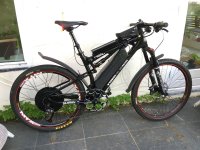
So if anyone can ever help me (and others) to get x4 temperature readout to the KtLCD3 display to work, that would be amazing! No problem if this needs to be changed manually in the code, I just need to know what to change exactly so we can monitor the motor temperature on the KtLCD3 display. And yes, I know temperature readout in the BluOsec app works very well, but at high speeds on downhill runs the easy accessibility of the LCD3 + buttons can be a matter of life and death... no time to touch the screen of my phone to change settings. My poor little 1500W motor is now running at some 7000 watts and produces a bit more heat than normal, despite loads of ferrofluid and heat sinks at the outside of the motor... ;)
 

Attachments

  • unnamed (2).jpg
    unnamed (2).jpg
    406.5 KB · Views: 1,492
stancecoke said:
atkforever said:
the wiki is wrong for this part, as I said above

Feel free to edit the wiki, everyone with a github account can write to the wiki. You can even add an own page for high voltage 18 FET controllers, if they need special actions. I have never used Kunteng controllers with more than 6 FETs and I don't use Kunteng controllers at all at the moment.

regards
stancecoke

Hi Stancecoke,

As I wrote in my previous post: many thanks to you for putting so much time and effort in this amazing piece of firmware, all these years. Also many thanks for still viewing posts on this forum and replying to them.

In response to your response: I have built up a reasonable amount of experience with the 18 fet controllers and this firmware. I don't think the controllers are really that different; you just need to circumvent some limitations of the current firmware/hardware combination (measurable ranges). If anyone is interested, I could write some tips and tricks in the Wiki (first need to register). Topics that could be covered:
- How to install buck converter
- How and when do you need to modify the LVC resistor
- How to optimize cooling for the mosfets
- How to massively enhance the power feeding traces
- How to select and add capacitors (electrolytic and CBB/snubber)
- How to convert 48v -> 72v
- How to calibrate voltage and current sensors and set up the parameters in the java configurator
- What are my optimized parameters for hub motors (35mm magnets and 50 mm magnets, 3T, 23 pole pairs, 120 degree hall)
- How to connect torque sensor (sempu t4) with external power supply
- etc etc

So if anyone is interested, just let me know. Otherwise I will just keep spamming this forum every now and then with random experiences and findings :wink:
 
I bought a flipsky vesc a few days ago but unfortunately it failed so I'm back to the KT controller again. Probably that is some sort of punishment for criticising the KT firmware, who knows. Probably the only way to get a reliable FOC controller on an ebike is to put a prius inverter on the damn thing.

While the vesc worked, it was miles ahead of the KT controller with far more powerful regen which could lock up the back wheel, easy auto setup, fast throttle response and absolutely no drag on the motor when coasting.

I am wondering how the regen is implemented in the KT firmware and if there is a way to get more current into the battery? Is it done by simply pulsing the three bottom fets in the h bridge?

I noticed that any current setting over 5 amps in the configurator tool results in no extra stopping power.

The vesc was maybe using synchronous switching during regen which explains how it was able to put more amps back into the battery.
 
Hi all,

I am new to this topic (Electric Bikes, not Electronics in general) and I just recently built my first ebike with a 12 FET squarewave controller, but I'm already planing on upgrading to a 18 FET controller, which should be running the OpenSource firmware.

I'd love to see an expanded wiki on how to modify the 18 FET controller to make it work well and reliably, that would help me a lot. :bigthumb:

Best Regards
 
Hello, everyone...
I am new in this forum and because of your project, i was motivated to sign up and share with you my thoughts and results by following step by step the wiki and from what i learned by reading a big part of this thread.(180 pages is huge... :shock: )
First of all i have a Kt S06S controller with an LCD5 screen and geared motor 250 W on 16 " ebike, 36V.
I have only , throttle and a 6 magnet PAS sensor, simple low brakes and external speed sensor.
I have two of those "sinewave" controllers , so i decided to flash one of them with your firmware.
Until now i succeed to find the correct parameters ( i believe so as you can see on the attachment) and the motor spins with the less current with no load. The problem i have is that, although i have checked the "assist lvl affects throttle" no matter i change assist level on the screen, nothing happens and the motor always spin at full throttle. Any ideas what i have to modify? Also the cruise control does not work although i hold the throttle continuously for over 10 seconds.
Last i noticed that the indications(symbols) at screen for PAS, THROTTLE and CRUISE never appears. I checked the code and i found the following:
Code:
	// prepare moving indication info
	ui8_moving_indication = 0;
	if (brake_is_set()) {
		ui8_moving_indication |= (1 << 5);
	}
	//if (ebike_app_cruise_control_is_set ()) { ui8_moving_indication |= (1 << 3); }
	//if (throttle_is_set ()) { ui8_moving_indication |= (1 << 1); }
	//if (pas_is_set ()) { ui8_moving_indication |= (1 << 4); }
I unmarked those on the code but there is no declarations and is more complicated for me to enable them.
On the opposite at old casainho code those indications works. Will you help me to enable them?
I really count to your help stancecoke and casainho and to all the good members of this community.
I am glad that i joined here and i hope to contribute with my help in the future.
 

Attachments

  • 20210710-194440EEST.ini
    243 bytes · Views: 34
The controller is current Limited so Will go to full speed in All levels but with different acceleration rates. Try a Roads test before changing the code :)
 
maxkoehler said:
Hi all,

I am new to this topic (Electric Bikes, not Electronics in general) and I just recently built my first ebike with a 12 FET squarewave controller, but I'm already planing on upgrading to a 18 FET controller, which should be running the OpenSource firmware.

I'd love to see an expanded wiki on how to modify the 18 FET controller to make it work well and reliably, that would help me a lot. :bigthumb:

Best Regards

Ok, two requests will count as people being interested. Don’t count on the wiki pages soon, tinkering with all the ebikes also needs time. I will try to write a bit about my experiences with the 18 fets. A new COVID lockdown could help :). Meanwhile, you can always as direct questions.
 
sylvain_wm said:
atkforever said:
Your voltage calibration is still set to 90? I guess u should use a value around 150 or even more for this kind of controller.
I tried but t doesn't change anything.
Thanks

@sylvain_wm did you manage to get your controller properly working by now? I suspect your problem was (also) with the voltage calibration factor like aktforever suggested. For a 72v controller you would need a value over 100 but the firmware does not allow that/respond to that. So for other users to get their controllers working at a higher voltage, you will need to hardware mod the lvc resistor so that the output is within limits of the adc conversion factors. See page 180 for some more explanation on my experiences with a 72v 18 fet controller.
 
honya96 said:
1N4001 said:
dr_lulz said:
using 18x IRFB4110
Why? Grab some CSD19536KCS instead, reduce RDSon by over a third. Might allow you to stick to 12 FETs too.

With both of these mosfets, use 20s li-ion max.

I tried 18fet swap to CSD mosfets and a 10A breaker trips when switching on the controller. (Without motor)

12fet stock fw and I think also this fw worked with these

I think that mosfet drivers may be too slow to sink the gate at 3 paralell (3x6), but I havent looked at it more.

If you plan to modify the drivers, please share.

You have 50A version of the current sensor, I think it will work up to 200A ok but there is 100,150, and 200A version too.

I am also thinking about upgrading the irfb4110 mosfets on a blown controller that I received from someone else. I am interested in the csd mosfets that keep popping up in this forum every now and then.

I understand that Honya96 did some experiments some years ago but was not successful yet with the 18 fet controller.
Did anyone ever get the csd19536kcs mosfets to work with this controller?

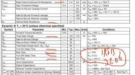
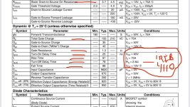
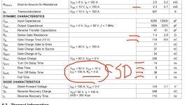
I am asking because i have an 18 fet controller that originally had irfb3206gpbf mosfets, which have remarkably similar timings, charge capacitances and internal resistances as the csd fets (see screenshots below). So, although i am not an electrotechnical engineer, my gut feeling would say that the drivers of an 18 fet kt controller should be able to drive the csds as well. It is my understanding that if the gate capacitance is lower, it should be easier for the mosfet driver to switch the mosfet on in time, compared to the irfb4110 fets.

Is there a mosfet expert that can shed some light on this based on the specs below: should the csd work with the driver for the 4110? I might actually need to/can lower Vgs from 15v to 12v to reduce the chance of ringing effects and reduce switching losses at the same time?

Probably i will just YOLO it with some csds once i get the blown controller to work again with the original fets (tk150e09ne)…

8AF87BFF-C73B-4031-AB42-ADA4652BD9F6.jpeg
D9E78092-A5A7-46BB-A077-FB63852641EB.jpeg
B26DEEDB-BF6C-4543-BA2C-6760BB72D853.jpeg
 
sdobbie said:
I bought a flipsky vesc a few days ago but unfortunately it failed so I'm back to the KT controller again. Probably that is some sort of punishment for criticising the KT firmware, who knows. Probably the only way to get a reliable FOC controller on an ebike is to put a prius inverter on the damn thing.


I noticed that any current setting over 5 amps in the configurator tool results in no extra stopping power.

Maybe it was punishment, maybe it is a chance to finally experience the kt controllers with custom firmware in all their customizable glory and have cheap yet powerful controllers available to you for the rest of your life (as long as china provides them) ;)!

Anyway, regen should be able to be much stronger with the custom firmware. I can set it to 40 amps and lock the rear wheel. Did you set the overvoltage protection high enough so that the controller get rid of all the power that the motor is generating? Is your bms a limiting factor (battery/single row full)?

With respect to the throttle response: there is a delay timer somewhere in the code, that limits the time it takes for pwm to reach its full value. By default it is set at 2 seconds; i set mine at 0,5seconds but you can probably go lower/more aggressive if you want. I think this timer is in adc.c? Need to check when i am back home.

Also, you could increase the kp and ki values; mine are set at 0.7 and 0.2 respectively. Too high values can result in overshoot for the feedback loop and in burned fets, so as always everything is at your own risk.

If you take small steps with each setting, you can tune the controller exactly as aggressive as you want. I have built 5 of these controllers and i am beating the fets to their maximum ratings (or slightly over..), but still have not managed to kill any controller yet.

So hopefully your punishment can change into satisfaction with a truly personal diy controller based on the great work that casainho, stancecoke and xnyle did!
 
stancecoke said:
sdobbie said:
if I add speed to that by turning the pedals, it starts consuming power

very strange, the current reading from the internal shunt say's clearly, that there is slight regen. No idea where a positive current should come from, that not passes the shunt :?

I'm using a BionX IGH3 direct drive with a Kunteng 6 FET and this firmware on my bike for my daily commuting, I have no drag at all. So I can't help any further at this.


Regarding switching PWM on while the wheel is turning: You have to know the kv constant of your motor excactly, then you can preload the PI-control to have the correct dutycyle directly at the start of the PWM. I've implemented something similar to optimize the regen at low speed. But I won't make it a feature in this firmware, as it carries a massive risk to burn your controller.

regards
stancecoke

Stancecoke, i would like to experiment with the pwm off during coast option.i have searched this forum but cannot find a detailed description of the steps that one needs to take to set this up for a specific motor. could you provide a bit more detailed description of how to determine the motor constant for pwm off and where to enter this value in the code (master branch)?

In fact, i have already started using this option without setting the motor specific constant. So far, the default value seems to work. It has enabled me to set the adc correction a bit lower (-1) without the motor spinning by itself after startup. It behaves very well during coast and after regen, without additional drag. But probably it is better and safer to set my motor specific constant correctly. So therefore my question for a more detailed ‘how to’ with a big disclaimer that everything is at our own risk ;)

All help is highly appreciated!
 
Iambuilderman said:
where to enter this value in the code (master branch)?

the factor for regen is hardcoded in this line:
https://github.com/stancecoke/BMSBattery_S_controllers_firmware/blob/18fdd5ce9479425b2fba97a2997f7b2d5f4d27f5/ACAsetPoint.c#L200

and in the PI-control it's used as a variable here:
https://github.com/stancecoke/BMSBattery_S_controllers_firmware/blob/18fdd5ce9479425b2fba97a2997f7b2d5f4d27f5/ACAcommons.c#L72

Where it's initialised and where changed (by BlueOsec obviously) you can see, if you search for the variable name:
https://github.com/stancecoke/BMSBattery_S_controllers_firmware/search?q=flt_s_motor_constant

I have never used @Xnyles solution. In my fork, everything was hardcoded.
You have to log the dutycycle and erps at no load and find the constant = dutycycle/erps.
Calculate at different speeds, the value should not vary very much (as it is a constant :)).
For my BionX IGH3 the constant is 2.0, @Xnyles default setting is 1.5

I hope that helps :)

regards
stancecoke
 
stancecoke said:
Iambuilderman said:
where to enter this value in the code (master branch)?


I hope that helps :)

regards
stancecoke

Great, thank you for this detailed explanation! So if I understand correctly, I should look in your fork where the constant is defined (the line: float flt_s_motor_constant = 1.5) and then change that constant in whatever constant I have determined myself. Btw: i am doing this for the lcd3 configuration of the firmware; the Bluosec version has this constant as an input in the interface if I remember correctly? I am on holiday right now so can’t check… this firmware is far too addictive so new ideas keep popping up. I will try setting this constant correctly immediately when I get home. Many thanks for your help!
 
stancecoke said:
For my BionX IGH3 the constant is 2.0, @Xnyles default setting is 1.5

Sorry, I messed things up... The 2.0 on my IGH3 is for max regen. Xnyles 1.5 on his DD is for zero current... Both factors have to be found for a specific motor.

regards
stancecoke
 
stancecoke said:
stancecoke said:
For my BionX IGH3 the constant is 2.0, @Xnyles default setting is 1.5

Sorry, I messed things up... The 2.0 on my IGH3 is for max regen. Xnyles 1.5 on his DD is for zero current... Both factors have to be found for a specific motor.

regards
stancecoke

:bigthumb:
 
HI, I'm new to the forum

I've had a 52v 1500w hub motor system for well over two years now
I came across this open firmware and I'm intrigued to apply it to my setup, especially regen :D
I just wanted to double check if I can flash this firmware into my KT48ZWSRKT 18 mosfet controller with an LED 880 display since I couldn't get much info about this controller.

Thanks in advance :)
 
snips said:
I just wanted to double check if I can flash this firmware into my KT48ZWSRKT 18 mosfet controller with an LED 880 display since I couldn't get much info about this controller.

Copied from the wiki..

Q: Can I use a KT36/48 ZWS type controller

A: As the ZWS type has no phase current sensor, you can't use the simplified FOC with it. You can disable FOC in the setup by checking "Disable Interpolation", but the motor will not run with best efficiency in this case. Some energy will be wasted as heat. It's better to use KT36/48 SVP type.
 
Ah thank you, I've read the FAQ and was just wondering if it covers my KT48ZWSRKT 18 mosfet one
Another question, will the LED 880 work with the modified firmware (I only need power and light) or do I require an lcd one

I've ordered an ACS current sensor to make my controller compatible with simplified FOC, just have to wait until it arrives
Its looking promising from what I've read here, cant wait to set it all up :D
 
Can't help with the display question I'm afraid, I think the LED880 is a Kunteng product so you may get some communication if you use the KT-LCD3 option but I wouldn't bet on it.

If you only need power on and light it maybe easiest to dispense with the display altogether, just fit a by-pass plug on the controller display connector and use the main battery switch to power up. Then add a separate switch for the light and you're good to go...?
 
Yeah making a separate switch is plausible, a box with the switch and ammeter sounds good. Will just have to see if it works with the 880 first. Don't really need PAS options anyways since I use the bike like a motorcycle :D

Implementing bluetooth sounds interesting though
 
Update

The ACS sensor has arrived and installed in the ZWS controller, and simplified FOC works :D
The firmware is absolutely way better than I had anticipated, the motor runs completely silent now. It sounded like a tractor with the stock Kunteng firmware. And regen is strong and crisp. I also felt a little bit more torque when starting

Also, the LED 880 works to switch on and off the bike, as well as the lights. Only the battery meter doesnt work
I will just buy a bluetooth module and use blueosec though

Overall I'm very impressed at how much better it performs compared to the stock kunteng firmware
Thank you to stancecoke and all the other developers :)
 
Alright
I've been tinkering with the bike for a while now
Got the spec angle tuned in using stancecoke wheel-on-air method, Its on 244 deg with 1.5 amp drawn current
The motor runs smooth, but after some test rides. the motor gets warm but the controller gets pretty hot
Is this normal for an 18 mosfet controller? or maybe its the LM317. I currently have no idea
Im running it on a 14S battery with 20 amp battery max
Any help would be appreciated
 
Back
Top