DIY Toroidal Axial Flux PM

Thanks for all the info, I really appreciate it. I will definitely keep reading.

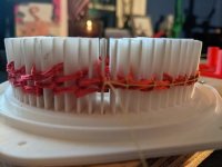
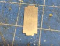
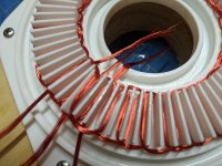
I tried the new winding jig... it didn't go great. Unfortunately the fins were too thin and they broke. I figured this might happen. they are 1mm thin, and they broke along the layer lines obviously. I could re-print the jig at a 45* angle, or I could print the pins separately on their side so the layer lines are perpendicular to the wires then assemble it. that would make it even easier to take out. Maybe Ill experiment with that

I hate wasting this wire.
resized-image-Promo - 2021-09-21T222811.004.jpeg
resized-image-Promo - 2021-09-21T222851.702.jpeg


Should have the new new meter tomorrow, so at least there's that
 
Just got the LCR meter. It's showing almost exactly 10uH phase to common, and 14uH phase to phase. So definitely on the lower end of things
 
Unfortunately I still am having issues with the printer. It got worse. Its no longer intermittent but the printer is full inoperable until I figure it out.

But I did talk to a friend who suggested another CNC/laser cutting service, and it was really cheap. Its called SendCutSend. For those in America, it might be a cost effective option.

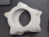
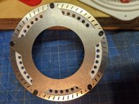
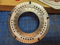
I got 10 parts, so I can break or bend one or two, and hopefully make a few pairs of rotors. I'm hoping to print a jig for the magnets, that will get epoxied into place, and possibly something to shroud the little fingers on the rotor, or this will be pretty dangerous to have your hands near if its spinning.

By making the fingers part of the rotor I'm hoping to add a bit more stiffness to the rotor without adding any thickness. Each piece weighs 50.5g, and are 1.5mm thick. The inner and outer diameter matches where the magnets will sit, so there is no more overhanging magnet, and hopefully will result in no flux leakage.

resized-image-Promo - 2021-09-29T140644.263.jpeg
resized-image-Promo - 2021-09-29T140709.670.jpeg

I'm going to redesign some parts too to see if I can make it more laser cut friendly since this service is cheap enough.
 
Just another small update. I ordered an entirely new heated print bed. Hoping that solves my issue with the printer so I can make a new jig for the stator. I have so many ideas.

I ordered a few more laser cut parts, lets see how they turn out. I ordered the parts to complete the rotor, with a spacer for the stator. I still need to design and print/order a part to carry the stator on the rotor. Also, I need to print/order the hub for the stator. I am hoping to use this service to solve issue I was having where the shaft for the stator was not a completely perpendicular to the rotor.

I am excited to see the parts show up. but I have to say I have a lot less excitement for these purchased parts as I do the DIY. damn printer. Hopefully its back in action soon.

I ordered 3 parts, a jig for the magnets in G10. and a ring for the outer diameter, and some impeller blades. (going to see if it will help at all)
 
I have read about some users building an insulated box around the 3D printer to hold the heat in, which reduces the energy needed to get the bed hot enough.

One side is see-through window, either glass or polycarbonate...
 
Registered just to pop in and say that this is really amazing and your creation of tools to make building things easier is pretty hilarious and rad. I was simultaneously impressed and laughing my ass off when I saw your wire winder.

Have you looked at Magnus' design and read their paper (pdf)? They go over a bunch of the justifications for their "production" design including not using Halbach and touch slightly on the winding pattern. Overall the math seems fairly trivial compared to the other stuff in this thread and and the forum, so if you haven't checked it out it'll probably be worth the perusal.
 
spinningmagnets said:
I have read about some users building an insulated box around the 3D printer to hold the heat in, which reduces the energy needed to get the bed hot enough.

One side is see-through window, either glass or polycarbonate...

Making an enclosure for my printer is definitely on my todo list. But I was able to replace the bed. I am just now getting a few test prints in. Hoping were back in action.


stranger-danger-zamu said:
Registered just to pop in and say that this is really amazing and your creation of tools to make building things easier is pretty hilarious and rad. I was simultaneously impressed and laughing my ass off when I saw your wire winder.

Have you looked at Magnus' design and read their paper (pdf)? They go over a bunch of the justifications for their "production" design including not using Halbach and touch slightly on the winding pattern. Overall the math seems fairly trivial compared to the other stuff in this thread and and the forum, so if you haven't checked it out it'll probably be worth the perusal.

Thanks for your interest. it has certainly been a lot of fun and there has been a lot of learning over the course of this project. To me, creating cheap specialized tools is something that a printer is great for. Prototyping too, but I know that the final or more optimized version of this will not all be printed.

I read through the paper and perhaps I am misunderstanding something but it seems like their conclusion was that more poles helped, and I was not able to discern anything about why they opted against the halbach in the paper.

I have also read that using back iron is better than simply using halbachs, but if you look in the first few pages of this thread. I did some FEMM analyses on back iron/halbach/both using the magnet dimensions that I am, and found that there was an optimization using 1.5mm of back iron in combination with the halbach array. Also, I found that the form of halbach that I used on my rotors allows for filling the gaps on the outer diameter of the rotor to further help prevent flux leakage, and since they are so thin. it doesn't add a lot of weight, while also increasing the total flux.
 
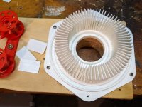
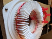
I was able to print out the 72 fins I needed and a new jig that receives them. I had to sand each one to make it a nice fit, then super glued them into place. I played around with a fin, because of the orientation of the layer lines, these bend and not snap. This should help prevent issues while winding. Unfortunately I am not able to fit the press over the top of all the fins, they just don't line up correctly.

I anticipated this being an issue and recently purchased some Kevlar thread which I will attempt to use to tie the bundles together tightly after winding. Then hopefully I can remove it from the jig in its shape, and press and epoxy it separately.

I do not have enough wire left on the spools since I wasted some on the last attempt, but I think I will just use what I have on there now, and practice tying the bundles.

resized-image-Promo - 2021-10-04T221605.175.jpeg

Also those other rotor parts I had laser cut will be here on Thursday-ish. Could have new rotors soon!
 
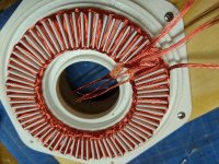
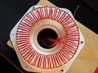
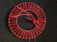
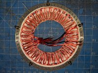
So I used the remaining wire on the spools and was able to get two complete turns, not great, but still allows for a proof of concept. with that wound, I tied it all together with the kevlar thread, which is great by the way. It was cheap, and I can pull on it all I want, and dont have to worry about it snapping.

This worked really well. Albeit, it would be difficult to automate, but I think I am a ways from that anyway. It only took about 30-45 minutes to tie both the inner and outer diameter, and Im sure it will go quicker next time.

Very happy with the results. Just need to respool the phase spools, and I might have another stator soon!

resized-image-Promo - 2021-10-06T224844.020.jpeg
resized-image-Promo - 2021-10-06T224907.351.jpeg
resized-image-Promo - 2021-10-06T224930.700.jpeg
resized-image-Promo - 2021-10-06T225006.889.jpeg
 
question for the crowd. Could Kevlar be used as tow? or would fiberglass work better. I would assume it depends on its ability to absorb epoxy. is that correct?
 
The new system is looking really good, printing separate dividers is ingenious! Threading the windings is looking right.

I built a Kevlar disc wheel back in the 80's using aircraft epoxy resin, which had a long drying time, so easier to
work in,.. but didn't notice any absorption issues.

Your epoxy might act differently if it doesn't have time to soak, but should work. Try a little test batch first.

Glad to hear you have your printer going again, nothing like losing the main tool. (My printer is still gathering dust,
so many other things to do,.. maybe this winter...)
 
cool, cool. I will probably incorporate that this time in winding the spools. but I will try the test batch first.

My custom parts didnt show up today, tracking info says Friday now, oh well.

A few other things that I am doing.
- I am making new phase spools that are a bit larger to hold more than enough for a stator.
- I updated the stencil for painting the fiberglass that will incorporate some changes in the next stator.
- I updated the hub to also incorporate the changes to the stator.
- I updated the winding jig to make it easier to tie the kevlar, and gave it wider fins on the OD to more evenly space things.
- I will print new fins to fit the new shape
- I made a separate jig for pressing and potting the stator

But I think the thing I am most excited about is this silly looking tool I made to help with holding the phase spool while I wind a turn. I tested this with the wire left on one of the phase spools, and it works better than I had expected. Its faster and easier to wind a turn now.
resized-image-Promo - 2021-10-07T161739.168.jpeg
 
HalbachHero said:
The litz wire is homebrew. I have created a winding machine with a combination of K'nex and 3D printed parts. Here's a video of it in action.
[youtube]cLb1yUehKk8[/youtube]

Brilliant HH. :bigthumb:

I need to make something like this but much larger to make my own hard laid cotton cord for some traditional rope work.

I think I may consider this for some coil making experiments. This earned you a new subscriber on youtube
 
fechter said:
Here's another crazy idea:

If you put little strips of iron lamination in the spaces between windings, it will greatly increase the torque/amp. While the iron adds weight, the increased torque will offset it and you may get a better overall power/weight ratio. The iron could just be pieces harvested from an old-school iron transformer core. The iron weight would be a small fraction of a typical iron stator.

Of course there will be some challenges keeping them in place and winding around them. Ideally you'd want little wedge shaped iron pieces but hard to make. Flat ones would be easy.

Core motor windings.jpeg

I got this idea from the Etek motor design. Worked wonders for those.

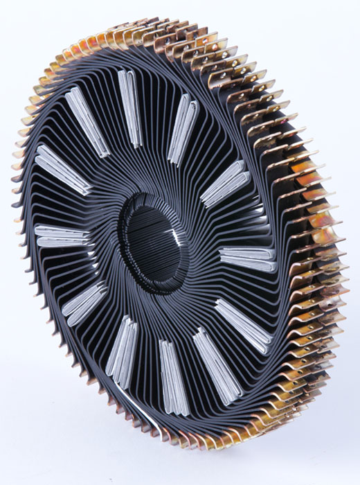
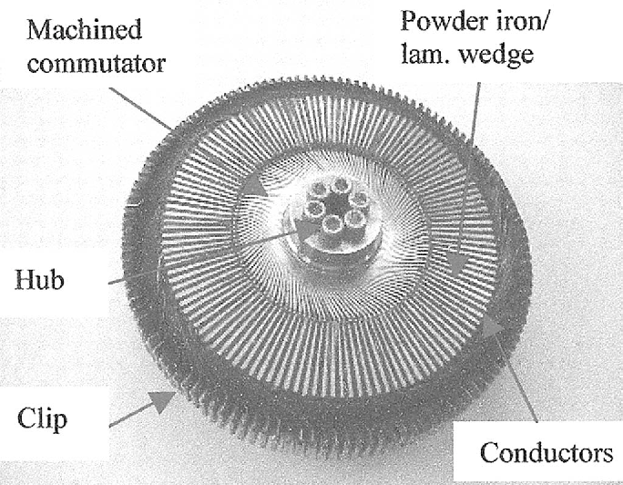
Fechter that is not a crazy idea... in fact it is now mainstream. Many manufacturers have copied the basic principle of the lynch motor but using their own improved designs for brushless versions. The Lynch motor is basically a easy to manufacture integer slot torus wound brushed motor with a ferrite stator armature ring with simple narrow slots on either side for the copper legs. The outside edge of the winding legs on the inside of the armature ring act as the motor's commutator. Oh and the armature spins while the "rotor" magnets remain stationary.

Here is an image of the unfinished unpotted armature without the center hub.

electric-marine-motor.jpg


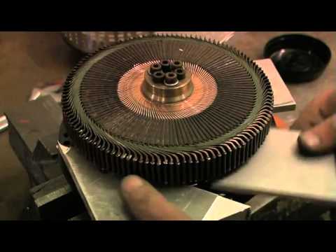
and completed armature.

hqdefault.jpg
and

2-Figure2-1.png


It is a brilliant stator design, which is why Saietta Group's brushless dual rotor axial flux motor stator looks so similar to the Lynch motor design they acquired by purchasing agni.

6a00d8341c4fbe53ef026be420c104200d-500wi


and several others do too including my favourite design, the Binova Flow...

Which leads me to ask, can I make a motor of this type using 3D printed armature that holds coil and ferrite elements to form the stator, and 3D printed rotors?
 
HalbachHero said:
fechter said:
On the Lynch motor, I think they used some kind of ferrite, like the SMC stuff... The Lynch motor has outstanding power/weight.

Optimizing may take some trial and error. The iron pieces should be the same width as the magnets and the more you can stuff in, the better, I would think. If angling them to fit around the copper helps, I don't think it would add much loss. It would be interesting to see how various thicknesses of iron affects the model. I could imaging sort of a zig-zag pattern for the iron. Like this, only the ends should be beveled so they are parallel to the rotor face.

slanted iron.png

The magnets are going to put a lot of force on them and they will want to slide out of the slots and bend the stator. Some kind of key or hole in the iron to lock them in place will be needed. Potting the entire core in epoxy might work, but epoxy gets soft when it gets hot. If there was any space left to blow air through the windings, it would help with cooling. Since the outer part of the winding will be exposed, a lot of heat can be extracted from that section.

I don't remember ever seeing a brushless motor built like this.

I think it's a really clever idea, but makes me think manufacturing that could be very difficult. Also given the potential for saturation, is it possible that having a 3d printed ferrous core would be a more suitable? Or would the ferrous material have to be isolated from each other somehow?

If the ferrous material needs to be the width of the magnet, might there be benefit in having thinner magnets to fit more poles?

fechter, The Lynch uses ferrite, ceramic comprised of iron oxide and other metals, die pressed and sintered. We can use laminations instead.

Yep the Lynch motor has outstanding power/weight. It uses integer slot winding scheme with 96 single loop copper coils and 8 magnets per side. In the Lynch motor the coil loops extend well past the stator core, so a new design which eliminates the loop extensions that form the commutator.

The pieces should be the height of the magnets, not the width. They will need to be secured post assembly. Epoxy will be fine. There are simple ways to create cooling paths from the coils to the exterior. I'd make slots in the edge of the 3D printed stator spider to lay in aluminum bars to make a heat sink.

I posted pics of a brushless motor like this in the thread on APL's build... the Binova flow uses this design, but with multiturn coils.

AM-JKLVDigXrLC-xXBTQ1TWTTHKN8kYyCa6r1v2zW5bTMDkJgv6XFrSoNIdPDKBqvyGCRfkxDfeKRCHevhugFaidG_xIzrf1ZUs7ShKkcGUImTqXJa9-pPSyyPfFrjQi5DGT42lmta3hLIFyd6Pwpml7ByHk=w935-h739-no


HH, using the lynch type single loop coil will make assembly simplicity itself and much easier than other windings. The modular nature and fast build times make it easy to use various materials for the ferrite and then compare the resulting motor characteristics to see how different the efficiencies are.

The copper coils can be cut from thin copper plates using any number of methods, and bent to shape on a jig or with sheet metal folding pliers. Then dipped in insulating red paint except for the very ends that are connected with clips. The parts then get assembled on a segmented 3D printed stator piece.

I'll have to model up what I am talking about to give you a visual
 
mxlemming said:
I'm moderately against the iron.

I've been quietly following this, resisting the temptation to add another project to my list but...

1) iron makes this much less diy able. As it stands now, i could print this at home, wind it, poke some magnets in and be basically done
2) APLs thread seems to have become a quest for ever more stiffness. It's not in any way a cheap diyable motor.
3) with no iron losses, you can just spin faster surely to gain power?
4) get lower kV by making an extra slice of rotor and stator? I think there are probably gains to be had like fewer magnets in the extra slices, no need for iron etc and the distances are larger than rotor to stator so less stiffness needed.

Just my 2c.

Instead of iron the DIYers can try 3d printed magnetic filament, or moulded epoxy with iron powder, or hand cut lamination steel and stack and bond them.

many applications want greater torque at lower rpms
 
TorontoBuilder said:
mxlemming said:
I'm moderately against the iron.

I've been quietly following this, resisting the temptation to add another project to my list but...

1) iron makes this much less diy able. As it stands now, i could print this at home, wind it, poke some magnets in and be basically done
2) APLs thread seems to have become a quest for ever more stiffness. It's not in any way a cheap diyable motor.
3) with no iron losses, you can just spin faster surely to gain power?
4) get lower kV by making an extra slice of rotor and stator? I think there are probably gains to be had like fewer magnets in the extra slices, no need for iron etc and the distances are larger than rotor to stator so less stiffness needed.

Just my 2c.

Instead of iron the DIYers can try 3d printed magnetic filament, or moulded epoxy with iron powder, or hand cut lamination steel and stack and bond them.

many applications want greater torque at lower rpms

I'll rephrase...
I'm against any magnetic materials in the stator because they result in massive stiffness requirements and will end up with the kind of kerfuffle APL has had.

You've posted an awful lot of pictures of companies motors in the last few days... Have you built any yourself?
 
TorontoBuilder,
Thanks for the kudos, I will get around to making a new version of it at some point, it has its quirks, and I don't event twist the wire any more, so the carriage does not rotate currently.

I think any concerns with 3d printing a stator part is the rigidity and the GT temp for the material. 3d printing metal could be a game changer. but still pretty expensive for a hobbyist

Modularity is important for rapid prototyping as you said, but also for mass production. I don't know if I intend to mass produce my motor, but I do intend to make more than 1. So I am certainly looking for ways to make things easier as I go.

I have tried the magnetic filament, Its neat stuff, but ultimately, its plastic, so heat becomes your worst enemy. Maybe if the goal is to print it, you could include a built in cooling channel for liquid cooling even.

With the recent way I've been making my stators, I am able to compress them down quite a bit to a point where I think by adding iron I am adding thickness to the stator for the same number of windings and same wire. I have thought about the idea of winding the turns and inserting layers of some ferrous material, but I would want it to be laminations perpendicular to the wire, and that makes it a lot more difficult to do with my current setup. Maybe down the road.


Mxlemming,
I agree that stiffness could be an issue. I was trying to bend the last stator I made (the one with fiberglass), and with enough effort I can see it bend. albeit, it bent more in some spots than others. I'm sure this has to do with the imperfect epoxy job. but adding metal would only make that more of a problem. So I will avoid it for now.


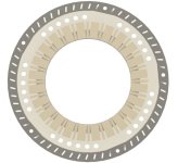
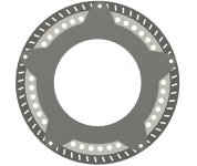
I was playing around with Fusion360's appearance settings and modeled what the rotors will look like with the custom parts I ordered.
resized-image-Promo - 2021-10-08T071926.790.jpeg
resized-image-Promo - 2021-10-08T071907.732.jpeg
Screenshot 2021-10-08 073639.png
 
Indeed, I think you're actually on a very good track Halbachhero. There are no end of motor start ups who are willing to take your money promising the world, throwing patents around left right and center but really they're all claiming world changing abilities for marginal gains and different manufacturability trade offs.

Just because it's patented doesn't mean it's good, it's useful, it's any better than anything else, or the patent is defensible. Just because someone wrote a technical paper about something or it comes from a university doesn't mean it's good, better or useful either.

One of the biggest and most popular motor providers for ultra high tech, maxon, uses coreless motors not dissimilar in concept to yours (though radial usually) almost exclusively for their brushed versions and I believe many of their brushless ones including their ebike hub offering.

Rotor stiffness is easier than stator stiffness since 1) the magnets have stiffness of their own and 2) they're usually backed by a lump of steel or embedded in something very strong to cope with the high radial accelerations. For stators, any added material for stiffness is lost copper.
 
mxlemming said:
TorontoBuilder said:
mxlemming said:
I'm moderately against the iron.

I've been quietly following this, resisting the temptation to add another project to my list but...

1) iron makes this much less diy able. As it stands now, i could print this at home, wind it, poke some magnets in and be basically done
2) APLs thread seems to have become a quest for ever more stiffness. It's not in any way a cheap diyable motor.
3) with no iron losses, you can just spin faster surely to gain power?
4) get lower kV by making an extra slice of rotor and stator? I think there are probably gains to be had like fewer magnets in the extra slices, no need for iron etc and the distances are larger than rotor to stator so less stiffness needed.

Just my 2c.

Instead of iron the DIYers can try 3d printed magnetic filament, or moulded epoxy with iron powder, or hand cut lamination steel and stack and bond them.

many applications want greater torque at lower rpms

I'll rephrase...
I'm against any magnetic materials in the stator because they result in massive stiffness requirements and will end up with the kind of kerfuffle APL has had.

You've posted an awful lot of pictures of companies motors in the last few days... Have you built any yourself?

So you're directly contradicting yourself now... you're not "moderately against iron, you're completely opposed, or just being a....?

To further sum up what you're trying to indirectly imply... if I have not actually built any electric motors my opinions are invalid.

regardless of my 30 year vocation in engineering and my 40 year avocation in live steam, ship and RC modelling...

The issues with APL's motor were mostly attributable to poor stator design choice and build. It has been adequately demonstrated that 3D printed materials can be successfully substituted in the place of traditional materials with proper design. The same applies here.

Do not fret, I will be posting my build thread for everyone else to view in due time, and FYI I have built several radial flux generators and motors in my live steam days.
 
Jrbe said:
I have an idea for the stator. Its not fully fleshed out yet but might help this along.

These are 2mm wide with a stack width in the middle of 6mm - no idea if thats ideal or not.. With this you could wind each group of coils then bolt them together. The 3 drive nubs on the inside double as holders for conductive bushings to get the power to the coils and also allow stacking of stators / jumping to the next stack / group. The notch on the right side (light grey outer stator) is for the wire routing between the groups (right side slot.)
Modular outer stators.PNG Stator stacked view.PNG Outer stator.PNG This would trap heat in the wire. Could add some holes to allow air in and out.

To add some strength you could add fiberglass tow to the wire as mentioned previously. There are also fiberglass and kevlar sleeves. These are woven tubes that can stretch and conform to different shapes. These could work well a few places here. I also keep thinking of a uv cure epoxy or maybe SLA resin could help as well.

jrbe, very nice idea for a modular stator design. mind if I use your model to play around with when I get my 3D printer?
 
TorontoBuilder said:
So you're directly contradicting yourself now... you're not "moderately against iron, you're completely opposed, or just being a....?

To further sum up what you're trying to indirectly imply... if I have not actually built any electric motors my opinions are invalid.

regardless of my 30 year vocation in engineering and my 40 year avocation in live steam, ship and RC modelling...

The issues with APL's motor were mostly attributable to poor stator design choice and build. It has been adequately demonstrated that 3D printed materials can be successfully substituted in the place of traditional materials with proper design. The same applies here.

Do not fret, I will be posting my build thread for everyone else to view in due time, and FYI I have built several radial flux generators and motors in my live steam days.

Now now, no need to bicker. Mxlemmings indirect implication is fairly valid. You had not presented your credentials, and have been only posting photos of other peoples work, and it's easy to use words that sound smart on the internet.

I can't wait to see what you come up with. Its great to see different ideas tried and vetted, and constructive criticism is totally valid.


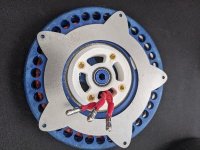
Custom parts arrived!
I put them together in a dry fit without the magnets. Looks pretty good. And just by some basic math, it should weight similar or about 10 grams heavier than the last version.
resized-image-Promo - 2021-10-08T135432.646.jpeg
resized-image-Promo - 2021-10-08T135346.016.jpeg

The slots on the outer ring are for little riser/fan blades that I had made. They probably wont work unless they were welded in place or something, but i'm going to try them out. I will probably use some form of risers first.
PXL_20211008_165110952.jpg
 
HH, I'd not gotten so far in your thread to see this portion of your design... very exciting.

I was not bickering, I merely pointed out someone else's issues.

sure anyone can post random pics, but not anyone can post images from multiple leading companies that illustrate exactly the concepts that are being explained... I know because I've been through endless sphere and haven't seen anyone making all the connections between all these companies, nor researching all their patents and manufacturing in the way I have.

My point is, I made my credentials by the content and logic of my posts.

Sorry to have commented on your thread, I bid you adieu.
 
TorontoBuilder,
Sorry if you were offended. You are more than welcome to continue posting ideas and discussion on this thread. No hard feeling :thumb:


So I was playing around with the new parts and put the 2 turn stator I recently wound over the custom stuff, and realized how much farther the stator end-turns lay beyond the end of the magnets on the OD. And a recent change to the jig would have exacerbated the issue slightly more. Looking at the model, sure enough the fins were longer than they needed to be, not sure how I missed that till now.

I remodeled the stator winding jig, but ill have to make some changes to a few other things and re-print.

The good new is, this could ultimately reduce the amount of wire used to make a stator with the same Kv, maybe not much, but I think the less resistance the better. I figure I saved 2-4mm for each pole in a phase, so something like 24-48mm per turn over 10 turns that's nearly a half a meter in each phase. As long as the end turn doesnt negatively react with the magnets, I think it will be an improvement.

This could also lead to a reduced overall OD as I might be able to shrink the rotor down, and obviously losing mass on the outer diameter is the best place to lose it

resized-image-Promo - 2021-10-08T151014.317.jpeg
 
Back
Top