DIY Toroidal Axial Flux PM

TorontoBuilder said:
Jrbe said:
I have an idea for the stator. Its not fully fleshed out yet but might help this along.

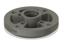
These are 2mm wide with a stack width in the middle of 6mm - no idea if thats ideal or not.. With this you could wind each group of coils then bolt them together. The 3 drive nubs on the inside double as holders for conductive bushings to get the power to the coils and also allow stacking of stators / jumping to the next stack / group. The notch on the right side (light grey outer stator) is for the wire routing between the groups (right side slot.)
Modular outer stators.PNG Stator stacked view.PNG Outer stator.PNG This would trap heat in the wire. Could add some holes to allow air in and out.

To add some strength you could add fiberglass tow to the wire as mentioned previously. There are also fiberglass and kevlar sleeves. These are woven tubes that can stretch and conform to different shapes. These could work well a few places here. I also keep thinking of a uv cure epoxy or maybe SLA resin could help as well.

jrbe, very nice idea for a modular stator design. mind if I use your model to play around with when I get my 3D printer?

Yeah, please, anyone feel free to use the idea.
I might look at building one when chips are no longer unobtanium and I can build a controller too. I'll share if I get anywhere.

Let's everyone try to be polite, I think we're all here for good reasons.
 
HalbachHero said:
So I used the remaining wire on the spools and was able to get two complete turns, not great, but still allows for a proof of concept. with that wound, I tied it all together with the kevlar thread, which is great by the way. It was cheap, and I can pull on it all I want, and dont have to worry about it snapping.

This worked really well. Albeit, it would be difficult to automate, but I think I am a ways from that anyway. It only took about 30-45 minutes to tie both the inner and outer diameter, and Im sure it will go quicker next time.

Very happy with the results. Just need to respool the phase spools, and I might have another stator soon!
Just spotted on this, your phase wires all run against each other. Is it worth adding some extra insulation between the wire bundles; when you clamp it it seems like a high risk of inducing shorts.

Re. Kevlar, i recently looked into this for work regarding belts. The numbers tend to be a bit vague but kevlar is definitely stiffer by ~30%. However, it has substantially higher thermal expansion which in the case i was looking at might result in loss of accuracy, and in this application could result in warping at temperature. Glass is very very stable by comparison.


TorontoBuilder said:
So you're directly contradicting yourself now... you're not "moderately against iron, you're completely opposed, or just being a....?

To further sum up what you're trying to indirectly imply... if I have not actually built any electric motors my opinions are invalid.

regardless of my 30 year vocation in engineering and my 40 year avocation in live steam, ship and RC modelling...

The issues with APL's motor were mostly attributable to poor stator design choice and build. It has been adequately demonstrated that 3D printed materials can be successfully substituted in the place of traditional materials with proper design. The same applies here.

Do not fret, I will be posting my build thread for everyone else to view in due time, and FYI I have built several radial flux generators and motors in my live steam days.

I think you might be overreacting a bit. The internet is a fragile place.

Please post your own build thread. I will read with great interest the direction you eventually take and the reasons why. We all read each other's posts and threads, your information posted there will be equally consumed, and in the context of "this inspiration led me to take these decisions and pursue the design presented here... And here's my result it's... Great/works with problems/terrible/..." Will be far better received.

FWIW I would love to see your radial flux generators posted... Perhaps start your thread and post them in the first 2 or 3 posts.
 
mxlemming said:
Just spotted on this, your phase wires all run against each other. Is it worth adding some extra insulation between the wire bundles; when you clamp it it seems like a high risk of inducing shorts.

Re. Kevlar, i recently looked into this for work regarding belts. The numbers tend to be a bit vague but kevlar is definitely stiffer by ~30%. However, it has substantially higher thermal expansion which in the case i was looking at might result in loss of accuracy, and in this application could result in warping at temperature. Glass is very very stable by comparison.

I assume you are talking about where the wires cross at the end turns. I have thought about adding layers of fiberglass as I wind things, but I would need to cut it in such a way that I think it would no longer provide any improvement on stiffness. I would have to cut slots for each fin, and that would result in a lot of short strands of fiberglass.

I am sure there is another material that might work too, I assumed that the enamel would hold up to being layed on top of other layers, and that once its epoxied, that it wont move, but maybe perhaps the wires will be able to vibrate enough to wear out the enamel coating over time.... not really sure.

The thermal expansion note about the kevlar is a good one. Thank you for mentioning that. I can understand how I would want to avoid materials from expanding and contracting inside the epoxy. I will probably end up getting some fiberglass tow on that note.


I am making another change to this stator, to mechanically attach it to the hub. I have modified the hub to support 8 heat inserts for 6mm M3 screws. I am hoping this allows me to reuse the hubs saving bearings, or not get stuck with realizing tolerances were off once I glue it all together. I am going to make the stator's ID a lot smaller, and fill it with epoxy where I can have holes to mount it. Also I am hoping this helps with stiffness, because there will no longer be a pivot point for the stator to bend on. Before it was only glued near the edge, and that caused it to easily delaminate from the hub in a few cases,
Screenshot 2021-10-09 101843.png
 
HH, if I understand right, you plan to use many separate fins for the fan, and some standoffs? One of the big problems
I had was with the rotor spacers. Might I make the suggestion to maybe 3D print the fan blades along with the standoffs
as a completed ring unit?

As for the general conversation of adding steel or not to the air core motor,.. air core motors are lighter because of no
iron, true, but they are not free from the flux forces that make the torque power. There's no free lunch, by the time
you get the same power as a steel motor, you get the same angular force.

Usually, the weight comes back as a transmission is added to lower the high rpm to a usable speed, and a liquid cooling
system to dissipate higher temps, or, along with the usual multi stators needed to gain higher start up torque.

More stators, more magnets, more stiffness,.. it all seems to come back to more weight, or width and bulk. I guess it
depends on the use of the motor, but used in a bicycle,.. I'm not completely convince there are any gains. (yet)
I do hold out hope though. :wink:
 
APL said:
HH, if I understand right, you plan to use many separate fins for the fan, and some standoffs? One of the big problems
I had was with the rotor spacers. Might I make the suggestion to maybe 3D print the fan blades along with the standoffs
as a completed ring unit?

I think that 3d printing them with the fan blades in place is the way to go for a printed parts, I can get exactly the curve in the fan blades that I would like, and have quite a bit of design freedom, but after talking to a friend he convinced me to think about the manufacturability of this, and suggested that more parts would not necessarily be worse if it was cheap to produce. I don't want to give up on printing, but some of the parts I have made are maybe too complex to be anything more than a cool 3D printed device.

Also, my lack of design and mechanical engineering skill were in full effect. I know tolerances were tight, but I wanted to see what I could get away with. All and all they all fit, but it would be impossible to work with if it had magnets in the rotors.

I think ultimately there should be a balance, and I agree totally with what youre saying I think as a single unit would be printable and ultimately a better impeller


APL said:
As for the general conversation of adding steel or not to the air core motor,.. air core motors are lighter because of no
iron, true, but they are not free from the flux forces that make the torque power. There's no free lunch, by the time
you get the same power as a steel motor, you get the same angular force.

Usually, the weight comes back as a transmission is added to lower the high rpm to a usable speed, and a liquid cooling
system to dissipate higher temps, or, along with the usual multi stators needed to gain higher start up torque.

More stators, more magnets, more stiffness,.. it all seems to come back to more weight, or width and bulk. I guess it
depends on the use of the motor, but used in a bicycle,.. I'm not completely convince there are any gains. (yet)
I do hold out hope though.

This is the reason I lose sleep. Those damn trade-offs. I agree about the same angular force comment, but there are no iron losses or cogging. which I really like, I just need more wire to do the same job aka copper losses. Maybe the holy grail is not fully air-core or ferrous-core. but some optimization of the two where losses are minimized.
 
HalbachHero said:
APL said:
As for the general conversation of adding steel or not to the air core motor,.. air core motors are lighter because of no
iron, true, but they are not free from the flux forces that make the torque power. There's no free lunch, by the time
you get the same power as a steel motor, you get the same angular force.

Usually, the weight comes back as a transmission is added to lower the high rpm to a usable speed, and a liquid cooling
system to dissipate higher temps, or, along with the usual multi stators needed to gain higher start up torque.

More stators, more magnets, more stiffness,.. it all seems to come back to more weight, or width and bulk. I guess it
depends on the use of the motor, but used in a bicycle,.. I'm not completely convince there are any gains. (yet)
I do hold out hope though.

This is the reason I lose sleep. Those damn trade-offs. I agree about the same angular force comment, but there are no iron losses or cogging. which I really like, I just need more wire to do the same job aka copper losses. Maybe the holy grail is not fully air-core or ferrous-core. but some optimization of the two where losses are minimized.

In a motor, normally the torque producing component is the cross product of flux and current i.e. perpendicular to both and therefore in the plane of your rotor. Forces in place are very easy to carry

In the iron core design, there is a constant force due to the magnetic remnance pulling the iron stator out of plane towards the rotor. This is a force bending the disc in its thin, weak axis. Even with high current you should not be devouring the stator due to magnetic field.

I'd say that if you're planning on mass producing these, you should be looking at injection moulding with stable glass filled high temperature polymers like PSU, PPSU, PEI etc.
 
I realize my last comment doesnt make much sense. I by a combination or air core /ferrous core. I simply meant not trying to prevent saturation. Adding some to increase the torque but not so much it compromises the stator. But still getting the rotors as close as possible


mxlemming said:
I'd say that if you're planning on mass producing these, you should be looking at injection moulding with stable glass filled high temperature polymers like PSU, PPSU, PEI etc.
Yeah this is exactly what I was thinking if I tried to take this further. The glass infused plastic is super strong and lightweight.
I know nothing about injection molding though to know where design limitations are. Laser cutting is easier for me to wrap my head around, and again cheap. But yeah if I ever started a company or something I think injection molding would make more sense from a price stand point.
 
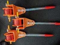
Ran out of the white filament, and since its October, orange seemed fitting. Made mostly printed versions of that goofy tool I made. Im calling it a phase winder.

I made three, one for each phase, and they are holding larger spools with (hopefully) plenty of wire for the 10 turns. Of the litz wire machine ran out on the last spool, and its 7 grams less than the next lightest, so hopefully it will be enough.

resized-image-Promo - 2021-10-12T090243.975.jpeg

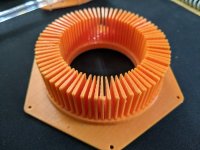
I also got the new jig model changed to reduce the OD of the stator. I printed and epoxied the fins into place. The fins on this are a bit wider to get the phases to space out a bit more evenly.

Just need to wind it up now.
resized-image-Promo - 2021-10-12T090302.772.jpeg

I'm in the process of making the jig for pressing/potting it now. should be done with printing all of that today or tomorrow if all goes well.
 
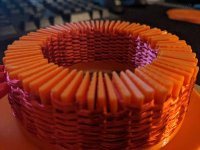
Well I spent the time to wind it up today. Unfortunately, the fins are not tall enough for all 10 turns, but I got 9. So 2 more than the last version, but not quite my goal. It didnt take too long to wind. Maybe 2 hours in total, but then I needed to tie it all together with the kevlar. This proved to be a challenge. It going, but I think I am not wrapping up some strands, and Im using a metal needle to thread it, which obviously is not ideal. Also the way Im tying things off, there is a reasonable chance that the gaps between some of the legs sort of collapse into each other. Otherwise tying it off really tightens it up on the jig and I can see a path to flattening it out further once its off the jig and in the press.
I spent over an hour tying things as well, and only made it about 1/3 of the way around the OD, and the ID will be harder I think.

I can see how some design tweaks to the jig could help, and maybe a ceramic needle, but it might break too easily....

resized-image-Promo - 2021-10-13T004556.819.jpeg
resized-image-Promo - 2021-10-13T004539.876.jpeg
 
HalbachHero said:
Well I spent the time to wind it up today. Unfortunately, the fins are not tall enough for all 10 turns, but I got 9. So 2 more than the last version, but not quite my goal. It didnt take too long to wind. Maybe 2 hours in total, but then I needed to tie it all together with the kevlar. This proved to be a challenge. It going, but I think I am not wrapping up some strands, and Im using a metal needle to thread it, which obviously is not ideal. Also the way Im tying things off, there is a reasonable chance that the gaps between some of the legs sort of collapse into each other. Otherwise tying it off really tightens it up on the jig and I can see a path to flattening it out further once its off the jig and in the press.
I spent over an hour tying things as well, and only made it about 1/3 of the way around the OD, and the ID will be harder I think.

I can see how some design tweaks to the jig could help, and maybe a ceramic needle, but it might break too easily....

resized-image-Promo - 2021-10-13T004556.819.jpeg
resized-image-Promo - 2021-10-13T004539.876.jpeg

Very cool. When I steal your design I plane on using electric steel laminations for the jig fins and leaving them in when potting the stator.

Nice night's work there sir. :thumb:

Oh and perhaps a sailmaker's sewing awl which has heavy needle and spool combined will work better for you?

[https://www.thechandleryonline.com/product_info.php?cPath=18_417&products_id=4071]
 
TorontoBuilder said:
Very cool. When I steal your design I plane on using electric steel laminations for the jig fins and leaving them in when potting the stator.

Nice night's work there sir. :thumb:

Oh and perhaps a sailmaker's sewing awl which has heavy needle and spool combined will work better for you?

[https://www.thechandleryonline.com/product_info.php?cPath=18_417&products_id=4071]

Thanks for the link, that handle would be really helpful to hold the needle in the direction I need to. even if I have to remove it to pass it through. I would rather tie things off the way I am now, instead of pulling the thread back behind the turns, but yeah that handle would be nice to have.

I am curious how you plan to press things down while the laminations are in place, and ultimately not have them protrude from the face of the stator. You posted a photo on APLs thread though that shows the folded metal sheet being used a "laminations". I think that's the most feasible from a DIY perspective, but I'm excited to see what you come up with
 
HalbachHero said:
I am curious how you plan to press things down while the laminations are in place, and ultimately not have them protrude from the face of the stator. You posted a photo on APLs thread though that shows the folded metal sheet being used a "laminations". I think that's the most feasible from a DIY perspective, but I'm excited to see what you come up with

I'm still curious about exactly how I will accomplish that task too. :lol:

I will be using a different style of winding more like that found in the Lynch motor where the outside radial portion of the coils will get fastened together with copper clips to give the stator structure.

I will likely use a multi-part and multi-step process and mould system that can likely be used regardless of the choice of coil styles.

Initially when assembled in the jig the laminations wont be centered in the stator, they will be shifted towards the bottom side in the jig slots. The idea is to assemble everything, then once flipped the laminations can fall into place equidistance between the coil's axial faces. BUT to get that to work right a mould will need to be assembled around the stator first to retain everything in position during the flipping procedure.

I'll be making my mould out of 3D printed TPE elastomeric filament, polished steel shafting and the outer shell out of PLA. The mould pieces get sprayed with mould release and therefore they will be reusable.

See my reference image I quickly drew up (and changed my idea just afterwards, lol), the center pin would now be polished shafting sized to match the bearings I may need to have in the stator depending. The shaft sets into an indent printed into the outer PLA shell for indexing the mould.

The white parts for the inner ring are only half of the elements to the inner edges, I've only shown one. They need to be sized to match the diameter of the bearings outer races. The idea is two rings like this create the pockets in the stator for the bearings.

AM-JKLWvf3vrPixziN_y45zfeG5UxeU8-PmJ7qCpFITNKZkTfe23x1BcX6Uihkwys2VUzZtlg-nSO4fWSD2BbPzS2DuSMThullhUezj_6Oov2bZDhQstJReVZ_UsVF05zO104gF3YLxDba7P6xtOmvDyusXb=w829-h484-no


The outside of the radial edge of the stator can have one TPE sleeve the full height of the stator, or one narrower sleeve to create an slot in the center of the outside of the stator, or two sleeves at the outside axial faces just like the inside to create indents to mate with bosses printed into the parts making up the motor can if so desired.

The idea is to set the steel shaft and the two elastomeric inner mould pieces into a hole printed in the jig after the laminations and coils have been placed, and after the outside or the coil elements have been connected in my case.

Then the outer elastomeric sleeve(s) placed around the stator coils. Then the outside shell placed over everything.

Then the whole jig and shell can be inverted. The laminations are then tapped down into the bottom of the shell to fix the correct position. Then the mould is cast.

Once hardened the mould is disassembled. voila, perfection itself, or so I hope.
 
HalbachHero said:
Thanks for the link, that handle would be really helpful to hold the needle in the direction I need to. even if I have to remove it to pass it through. I would rather tie things off the way I am now, instead of pulling the thread back behind the turns, but yeah that handle would be nice to have.

OH I forgot to add, you dont need to remove the needle when using the sewing awl. Have a look at the attached video link.

If you bind the outer and inner edges of the coils separately this will work for you, and the most difficult part of the operation will be to estimate how much kevlar thread you need to pull thru the first stitch or wrap you take to complete the entire stitching operation around the stator.

[youtube]https://youtu.be/SFx-NZP49d8[/youtube]
 
TorontoBuilder said:
Very cool. When I steal your design I plane on using electric steel laminations for the jig fins and leaving them in when potting the stator.

That's what I was thinking would be a good idea. Similar to the Lynch motor. You would still have some iron losses, but much less than a conventional stator. Semi-coreless.
 
TorontoBuilder said:
OH I forgot to add, you dont need to remove the needle when using the sewing awl. Have a look at the attached video link.

If you bind the outer and inner edges of the coils separately this will work for you, and the most difficult part of the operation will be to estimate how much kevlar thread you need to pull thru the first stitch or wrap you take to complete the entire stitching operation around the stator.

[youtube]https://youtu.be/SFx-NZP49d8[/youtube]

Thanks for the link. I see how it is supposed to work which is not exactly what Im going for. trying to bundle things in this fashion
http://www.aeroelectric.com/articles/cable_lace/cable_lace.html

and I do not understand how I would be able to bundle the wire like that as I went, because as I pull the awl out, the thread would follow. Im sure there is a different way to tie it that would work just as well to bundle it and would also work well with the awl. Ill spend some time googling this topic.


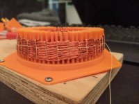
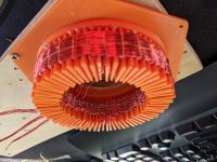
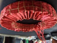
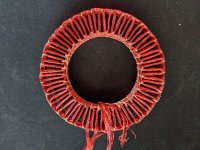
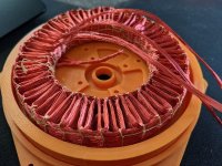
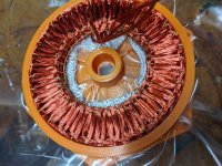
Check this out. I did a thing. Doesn't it look pretty?
resized-image-Promo - 2021-10-13T172506.148.jpeg
resized-image-Promo - 2021-10-13T172524.476.jpeg
resized-image-Promo - 2021-10-13T172546.262.jpeg
resized-image-Promo - 2021-10-13T172605.964.jpeg

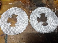
making the stencils for the fiberglass sheets, then I need to play with the press a bit more, Im having fitting issues, but I just changed the nozzle on the printer. so far so good.

Should be able to press/pot this thing soon.

Unfortunately the hub is larger on this version for the heat set inserts I plan on adding to the bottom, so It will not work with the previous rotors. I could try it on one half, but ill have to finish with the new rotors to truly call it Mk7, is that what im up to now??
 
Oh I see, that is different than I imagined. Much better off using a a heavy leather hand stitching needle.

I wrap my finger with a cloth band-aid when I do a lot of work pulling thread tight.

That stator looks so good I almost want to try it.
 
HalbachHero said:
and I do not understand how I would be able to bundle the wire like that as I went, because as I pull the awl out, the thread would follow. Im sure there is a different way to tie it that would work just as well to bundle it and would also work well with the awl. Ill spend some time googling this topic.


Check this out. I did a thing. Doesn't it look pretty?
resized-image-Promo - 2021-10-13T172506.148.jpeg
resized-image-Promo - 2021-10-13T172524.476.jpeg
resized-image-Promo - 2021-10-13T172546.262.jpeg
resized-image-Promo - 2021-10-13T172605.964.jpeg

making the stencils for the fiberglass sheets, then I need to play with the press a bit more, Im having fitting issues, but I just changed the nozzle on the printer. so far so good.

Should be able to press/pot this thing soon.

Unfortunately the hub is larger on this version for the heat set inserts I plan on adding to the bottom, so It will not work with the previous rotors. I could try it on one half, but ill have to finish with the new rotors to truly call it Mk7, is that what im up to now??


I am very confused. Having been making thinner and thinner stators to get the strongest flux, you now have one about an inch thick. Did I blink and miss something?
 
mxlemming said:
I am very confused. Having been making thinner and thinner stators to get the strongest flux, you now have one about an inch thick. Did I blink and miss something?

I need to press it, this is how the 7 turn stator was too, except I never removed it from the jig, it just wants to bunch up from being turned. Once I press/pot it, it should be less than 6.5mm.

I made some fiberglass sheets for the top and bottom like I did with the last. I made 4 this time, and will offset them 45 degrees.

The one thing I found that will be an issue though is that the stator wants to collapse into the inner diameter as I press it, instead of just down. I was thinking of making a ring to hold it up while I press it but im not sure I will have the clearance to the screws that will go in the center
 
Well folks, the results are in.

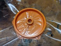
First let's talk about the plan. I was going to lay some plastic down over the mold, spray the parts with a mold release (cooking spray since the internet said that should work). Put the inner wall in place, then the outer wall. then lay the bottom sheets of fiberglass, the sheets offset by 45 degrees. Then insert the stator. Fill mold with epoxy. lay the top two sheets of fiberglass, then more plastic, and the cover of the mold. then press it all.
After some time I thought I would be able top push out the center hub piece before it was all cured, and press it down again till it was done.

This is not exactly how it went down.


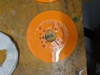
everything looked good until the do or die moment, except for one really important step. I did not cut holes in the plastic sheet for the wires to run through ahead of time. I had already mixed up the epoxy and then it started curing immediately experiencing the thermal runaway that it did last time I used a bunch. However, since this was in the mold when it got real hot. I was able to get the top of the mold on sort of in time, but since I didn't cut holes in one sheet of plastic ahead of time, I decided to go without, thinking I could peel the top off, but the mold itself melted and allowed the stator to expand even while pressed down. This also caused it to be nearly impossible to remove the middle part. So I had to chisel it out, and I saw a few wires that broke in the process of cleaning it all up. So, I think that this stator is toast before it could even be used.

I has identified a number of problems that I ran into while winding things, and while pressing/potting this thing, and I feel like I have a better idea on how to do it again, except for dealing with the thermal runaway. I feel like the mold would have to be metal in order to not melt and be rigid enough to be pressed.
I also think there must be a better way to press and pot the stator, but I dont understand how I would be able to press it in a vacuum bag without the phase wires ending up in the epoxy. I realize the way I am going about it is not ideal, but I suppose I dont understand what Ideal looks like

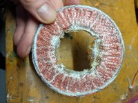
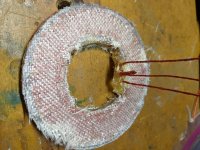
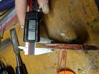
Anyway. heres some photos.
resized-image-Promo - 2021-10-15T214625.870.jpeg
resized-image-Promo - 2021-10-15T214647.062.jpeg
resized-image-Promo - 2021-10-15T214822.020.jpeg

At this point I cut the fiberglass, because I was feeling less confident about getting the hub part out if it was covered in fiberglass, so I cut out the parts where the holes would line up.
resized-image-Promo - 2021-10-15T214729.267.jpeg

resized-image-Promo - 2021-10-15T214849.497.jpeg
resized-image-Promo - 2021-10-15T214749.028.jpeg

You can see here the huge variability in thickness
resized-image-Promo - 2021-10-15T214909.860.jpeg
resized-image-Promo - 2021-10-15T214928.215.jpeg
 
That's unfortunate.

How are you planning on attaching the stator to the hub?
It might be worth adding some consumable / mold in place features to help hold it together and key the stator to the hub. You could also print a mold in place stator frame and hub like you'd see in a washing machine motor then pot it if you want. You should be able to print with some high temp plastics so this is doable.

How are you pressing the hub? You could look at using shoulder bolts or spacer collars evenly spaced inside and out so it's consistently clamped down at a specified distance vs fighting high and low spots with pressure / vacuum. Vacuum can help remove air pockets and can work magic with vacuum infusion to fill the resin. But it seems like there might be some thickness irregularities that you won't want to use high or any vacuum as it cures.
You could also add in some sprues to allow excess resin to escape, not spill, then cut / snap them off flat when it's set.

Epoxy can definitely suffer from thermal runaway if is too thick. I'd imagine a potting resin would be more stable for you or maybe using a longer cure time resin.

Elmers glue can be watered down and used as a cheap PVA. PVA is a water washable mold release that can be really helpful if it's used properly.

Is it worth practicing with a string wound stator (no copper, maybe woven nylon string about the size of your wire) to practice and work out the process bugs?
 
HH,

I wonder if you may have better and more consistent results with a silicone mould so you dont have to use plastic liner as you are.

Also, perhaps a less viscous and slower setting epoxy resin that you can add small glass fibers to. I've had very good results making close tolerance reinforced parts that way. Ditch the glass mats that way too
 
Your almost there HalbachHero, don't get too discouraged, everything looks great until the epoxy enters the picture. :thumb:

I agree with Jrbe in that it might be better to do some trial runs with something other than the actual stator copper
until you resolve these potting issues. Not sure what though,.. maybe some string and scrap copper mix?

Keep it simple and just work on the potting methods?

Slow curing epoxy is supposed to be stronger, and doesn't get as hot, so maybe that's a way to go,.. but you also need
it to be viscous so that it soaks into things. I would hit the net and research epoxy's, maybe there's something better
suited for this job.

Keep up the good work, setbacks are how we learn. :wink:
 
Hello HH.. just registered to comment some amateur questions/ideas that may not be helpful.
I can't remember how I found this thread, but I've been coming back to see your progress over the last few months and it's really caught my imagination. I've gone from pen and paper to SketchUp and Blender, trying to work out what's in my head..

So, I was wondering about 3d printing as much of the machine as possible.. it seems that the highest quality metal printers are still out of reach for most of us, but there's at least one company selling pla filament with 90% copper content, which (they say) works with most printers. I think it then requires firing in a kiln, so printing with a dual filament printer and isolating the copper with more pla would be out of the question.. but they also have a similar filament with 90% ceramic powder content.

You can see where I'm going with this.. So, any obvious problems with this train of thought?
 
Xer077 said:
So, I was wondering about 3d printing as much of the machine as possible.. it seems that the highest quality metal printers are still out of reach for most of us, but there's at least one company selling pla filament with 90% copper content, which (they say) works with most printers. I think it then requires firing in a kiln, so printing with a dual filament printer and isolating the copper with more pla would be out of the question.. but they also have a similar filament with 90% ceramic powder content.

You can see where I'm going with this.. So, any obvious problems with this train of thought?

The burn out temperatures need to be very precise, so you need a digital PID controlled kiln or metal heat treatment oven. They also make an Inconel filament, which as soon as I get my 3D printer and iron out the bugs I will try, because I need to make custom Lugs. I commented in the past about 3D printing copper using a service bureau, but I will give this a try too.

Oops, almost forgot the link to virtual foundry

https://shop.thevirtualfoundry.com/
 
Jrbe said:
How are you planning on attaching the stator to the hub?
It might be worth adding some consumable / mold in place features to help hold it together and key the stator to the hub. You could also print a mold in place stator frame and hub like you'd see in a washing machine motor then pot it if you want. You should be able to print with some high temp plastics so this is doable.
This is actually sort of what I attempted. I tried to make a part of the press that would create the negative space for some screws that would ultimately screw into some heat set inserts that I would put on the underside of the hub. Ultimately the inner diameter was going to just be epoxy. Then the hub itself would be a separate piece entirely. I could likely drill the holes for the screws after the fact if this is the way I end up proceeding.


Jrbe said:
How are you pressing the hub? You could look at using shoulder bolts or spacer collars evenly spaced inside and out so it's consistently clamped down at a specified distance vs fighting high and low spots with pressure / vacuum. Vacuum can help remove air pockets and can work magic with vacuum infusion to fill the resin. But it seems like there might be some thickness irregularities that you won't want to use high or any vacuum as it cures.
You could also add in some sprues to allow excess resin to escape, not spill, then cut / snap them off flat when it's set.
I'm sure the press that I have made could be improved quite a bit. Its essentially a plastic shell and I am using 4 clamps that each have a 300lb capacity If I recall correctly. I just clamp them down evenly around the top and bottom of the press. Shoulder bolts could certainly be helpful here. But the plastic shell essentially makes a spacer that limits it from being pressed thinner than 6.5mm. the irregularity in height was directly related to the epoxy curing too quickly.


Jrbe said:
Epoxy can definitely suffer from thermal runaway if is too thick. I'd imagine a potting resin would be more stable for you or maybe using a longer cure time resin.
This seems to be the consensus. Unfortunately I have not found another "high temperature" liquid epoxy with a longer cure time. So I may have to settle for a weaker epoxy.


Jrbe said:
Elmers glue can be watered down and used as a cheap PVA. PVA is a water washable mold release that can be really helpful if it's used properly.
I've not heard of this. I will look more into it. Thanks for the tip.


Jrbe said:
Is it worth practicing with a string wound stator (no copper, maybe woven nylon string about the size of your wire) to practice and work out the process bugs?
Yes. Absolutely. I am tired of wasting the copper and woven nylon might work well so I don't have to make the litz wire. easy peasy. great suggestion. sometimes I'm a glutton for punishment.


TorontoBuilder said:
I wonder if you may have better and more consistent results with a silicone mould so you dont have to use plastic liner as you are.
I've thought of making a silicone mold for parts of it, but 1. I have not done something like that before, so just another learning experience. 2. The plastic bags are really cheap and effective as long as its a flat surface.
I'm not opposed to silicone, but I don't think I'm quite there yet.


TorontoBuilder said:
Also, perhaps a less viscous and slower setting epoxy resin that you can add small glass fibers to. I've had very good results making close tolerance reinforced parts that way. Ditch the glass mats that way too
Do you think that the glass fibers would add more stiffness than the sheets? the sheets are easy to work with, and only add a negligible thickness with the 4 or so I have used. I like the Fiberglass tow idea too, I think that could be even easier to work with, and I wonder if it would allow me to ditch the sheets too. I may try a number of tests to see what works best.


APL said:
Keep up the good work, setbacks are how we learn.
Totally, and thanks for the suggestions. I agree, testing will be a quicker/cheaper path of iteration


Xer077 said:
Hello HH.. just registered to comment some amateur questions/ideas that may not be helpful.
I can't remember how I found this thread, but I've been coming back to see your progress over the last few months and it's really caught my imagination. I've gone from pen and paper to SketchUp and Blender, trying to work out what's in my head..

So, I was wondering about 3d printing as much of the machine as possible.. it seems that the highest quality metal printers are still out of reach for most of us, but there's at least one company selling pla filament with 90% copper content, which (they say) works with most printers. I think it then requires firing in a kiln, so printing with a dual filament printer and isolating the copper with more pla would be out of the question.. but they also have a similar filament with 90% ceramic powder content.

You can see where I'm going with this.. So, any obvious problems with this train of thought?
I too am subscribed to Integza on YouTube. if that's not what you were referring to, check him out. He's got some neat content.
I also started by 3D printing as much as I could and that will get you pretty far if you are willing to sacrifice, some size and performance. I think that conventionally manufactured parts are simply going to be more suited for the stresses of this type of machine. A professionally 3D printed motor might be more capable, but as you mentioned metal printing is still a bit out of reach for hobbyists.
I think that there is potential in making some parts using the metal filaments, but I think you will not achieve accurate or consistent tolerances due to how this material shrinks through the firing process. This is partly why I didn't venture down this path. But also, because there's a lot of prototyping that could be done with plastic prior to that, but honestly, I don't have any first hand experiencing working with such materials to really give a solid opinion. TorontoBuilder seems to have more knowledge than I do about this subject.
As far as ceramic goes, I have considered trying to work with that because it seems like a viable heat-sink that will not interact negatively with the magnetic field of the rotors, but it still has the same issues, and I worry it my be brittle
Please if this is something you wish to pursue I would encourage you to make a thread. I've had a lot of fun posting here, and I've learned a ton
 
Back
Top