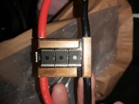
FLIPSKY new 20s 100A tiny controller (vesc based)

My assumption about the driver was "Will do fine, doesn't have a hard job here anyway (driving a single FET per output)"
And the whole thing is 100$ (+tax & shipping). I don't expect it to have the best parts with all the bells and whistles anyway. A purpose built gate driver for EV applications is cool.

mxlemming said:
I'm more interested in the low side topology, I built a VESC based controller with low side shunts and it really hates low inductance motors. Everything checks out perfectly but... Still just behaves a somewhat badly.

Why might that be? (my intended use case for this is with a 80 kv-ish 80100 motor, which will not have much inductance).

Br,
 
badgineer said:
My assumption about the driver was "Will do fine, doesn't have a hard job here anyway (driving a single FET per output)"
And the whole thing is 100$ (+tax & shipping). I don't expect it to have the best parts with all the bells and whistles anyway. A purpose built gate driver for EV applications is cool.

mxlemming said:
I'm more interested in the low side topology, I built a VESC based controller with low side shunts and it really hates low inductance motors. Everything checks out perfectly but... Still just behaves a somewhat badly.

Why might that be? (my intended use case for this is with a 80 kv-ish 80100 motor, which will not have much inductance).

Br,

80100 motor will have a sensible amount of inductance. My 70kV 8080 has 45uH, my 50kV Alien one is 62uH. You won't have much trouble running that.

The 12070 motors are the silly low inductance ones -I am measuring about 6uH for the Ant Innovation 62kV (nominal) one and the Turnigy 150kV one is a fricken nightmare at 4 milliohms and 1.6uH. It's basically a dead short with 6AWG wire.
 
Ive had issues with a flip vesc 6.6 running a dualtron motor on 12s and 40amp, even when i lowered the battery setup it would stall and make a horrible sound after 2 attempts and a few hours trying to change parameters i got it to turn but was not inspiring.

A hoverboard motor on the other hand was plug and play almost if the connectors was the same soon as it finished the tests it run like a champ 3× rated power.

I didnt have a low inductance value im sure it was around the 80uH mark, im wondering if it was a capacitance issue as the motor is so big compared to what a vesc normally sees other than that could have been a failed gate shunt messing my FOC up as i got sensorless to spin but its all guesses i potted the controller so its a bin job.
 
Sorry to hassle you again, what's the DCDC converter chip? Probably the big one next to the inductor.

That would be an LM5161 and another chip marked "708 303 GAMB" I believe is a voltage regulator but can't find anything on it.
 
Ianhill said:
Ive had issues with a flip vesc 6.6 running a dualtron motor on 12s and 40amp, even when i lowered the battery setup it would stall and make a horrible sound after 2 attempts and a few hours trying to change parameters i got it to turn but was not inspiring.

Were you running it sensorless ?
 
atkforever said:
Ianhill said:
Ive had issues with a flip vesc 6.6 running a dualtron motor on 12s and 40amp, even when i lowered the battery setup it would stall and make a horrible sound after 2 attempts and a few hours trying to change parameters i got it to turn but was not inspiring.

Were you running it sensorless ?

I couldnt turn it in with foc it kept looking up but sensorless it would spin to full speed but still lock up occasionally then flash a yellow light and start all over again.
 
Ianhill said:
atkforever said:
Ianhill said:
Ive had issues with a flip vesc 6.6 running a dualtron motor on 12s and 40amp, even when i lowered the battery setup it would stall and make a horrible sound after 2 attempts and a few hours trying to change parameters i got it to turn but was not inspiring.

Were you running it sensorless ?

I couldnt turn it in with foc it kept looking up but sensorless it would spin to full speed but still lock up occasionally then flash a yellow light and start all over again.

You're not the first out the last to struggle with VESC and these scooter motors, I've had this issue too. They tend to be insanely low inductance (like sub 10uH) and not have a great BEMF profile which makes them horrid to drive with any controller... And the more "cleverness" in the control loop the less likely it is to work frankly.
 
Thats a pity the 72v vesc varients would have made a lovely smooth ride with variable regen, hoveeboard motors run impressively well shame these don't.

I see kaabo uses a one piece rim on the warrior to help balancing at high speed as a pair they run 7.4kw but the rion use a single hub on the rear thats more powerful than the pair.

This got me thinking do rion use an custon axial motor to get the power density higher while managing the added heat that comes with it, if the hubs were swapped from radial to axial with a decent design a 6.5 hub motor could be capable of around 10kw per unit.

Id love to see a taredown of a rion hub see what they have done.
 
My Flipsky just arrived and I did some workbench tests with a Ninebot G30D Motor.

I tested 13S6P and planning 20S6P.

Is there any on/off switch option that I missed?

Do I really need an external antispark switch to poweroff my Flipsky?

Sorry, but I am new to VESC...
 
You will need a antispark switch for ease of use.

You can make a 2 stage switch with a resitor to power up the capacitors slowly then switch over.

I find the antispark switches good even if i broke one.

You can roll the scooter forward the switch detects the motor emf and switches on after a set period of time it switches off automatic.

Makes the ride easy to pick up and ride off so best add a safety switch or disconnect for theft etc but to see the plod lurcking and a quick push and twist your off catch me later.
 
Ianhill said:
You will need a antispark switch for ease of use.

You can make a 2 stage switch with a resitor to power up the capacitors slowly then switch over.

I find the antispark switches good even if i broke one.

I found some DIY schematics. So I will build a 2 stage switch. This way I know how to repair if it fails.

I have another question: my second FLIPSKY arrived today.

I want to pair them via canbus. Now someone told me, I have to switch them both on/off.

If I only power one of them on, it could blow the canbus chip.

Is this true?
 
speeed said:
Ianhill said:
You will need a antispark switch for ease of use.

You can make a 2 stage switch with a resitor to power up the capacitors slowly then switch over.

I find the antispark switches good even if i broke one.

I found some DIY schematics. So I will build a 2 stage switch. This way I know how to repair if it fails.

I have another question: my second FLIPSKY arrived today.

I want to pair them via canbus. Now someone told me, I have to switch them both on/off.

If I only power one of them on, it could blow the canbus chip.

Is this true?

The canbus dies like to fail during power up/down

My understanding is that this is due to the controllers losing their ground connection between them. If you unplug and the ground breaks first, positive second, the canbus chip sees the full battery voltage across it and there only designed to have functional isolation up to about 40V.

So i guess... Run them from the same connector? Have a permanent thick ground wire between them?

This hasn't ever happened to me, I've only been diagnosing cause of death for others.
 
mxlemming said:
The canbus dies like to fail during power up/down

My understanding is that this is due to the controllers losing their ground connection between them. If you unplug and the ground breaks first, positive second, the canbus chip sees the full battery voltage across it and there only designed to have functional isolation up to about 40V.

So i guess... Run them from the same connector? Have a permanent thick ground wire between them?

This hasn't ever happened to me, I've only been diagnosing cause of death for others.

Hm, running them from the same Connector means they are both loosing ground first, because all antisparcs are switching ground.

This could be seen as a "controlled shutdown" as both VESC are runnig on the capacitors until they are discharged.

But what happens, if a FET blows up kills the traces on the powerrail. This will shut down at least one of the FLIPSKYs.

I would prefere one fuse on the plusrail and one DIY antisparc with 4 parallel FETs on minus for every Flipsky.

The battery cables on the FLIPSKY are looking like 10awg. This is why I want to place the fuse and the antisparc close to the connector of the VESC.

Behind the fuse and the antsparc I would use thicker wire to batterie plus and minus.

But I want to be shure that my thoughts are right and I don`t have a total loss of both FLIPSKYs if one FET blows up.

With 20S I am on the upper Limit, so I don`t want to make any mistakes.
 
Never run dual myself, i can guarantee i would have blown one its my luck.
 
speeed said:
mxlemming said:
The canbus dies like to fail during power up/down

My understanding is that this is due to the controllers losing their ground connection between them. If you unplug and the ground breaks first, positive second, the canbus chip sees the full battery voltage across it and there only designed to have functional isolation up to about 40V.

So i guess... Run them from the same connector? Have a permanent thick ground wire between them?

This hasn't ever happened to me, I've only been diagnosing cause of death for others.

Hm, running them from the same Connector means they are both loosing ground first, because all antisparcs are switching ground.

This could be seen as a "controlled shutdown" as both VESC are runnig on the capacitors until they are discharged.

But what happens, if a FET blows up kills the traces on the powerrail. This will shut down at least one of the FLIPSKYs.

I would prefere one fuse on the plusrail and one DIY antisparc with 4 parallel FETs on minus for every Flipsky.

The battery cables on the FLIPSKY are looking like 10awg. This is why I want to place the fuse and the antisparc close to the connector of the VESC.

Behind the fuse and the antsparc I would use thicker wire to batterie plus and minus.

But I want to be shure that my thoughts are right and I don`t have a total loss of both FLIPSKYs if one FET blows up.

With 20S I am on the upper Limit, so I don`t want to make any mistakes.

One anti spark for both and you avoid the switching issue even if it's switching ground. Two anti sparks at 20s and you have immediate problems with the CAN. You'll be lucky not to kill it.

As long as there is always a solid ground wire between both flipsky ESCs it won't experience this problem.

If one FET (on the flipsky, not the anti spark) dies, there's no reason for it to kill the other ESC, but they might both have the same cause of death (over voltage is the most common FET killer) and nothing will protect against that except VESC firmware itself. A FET dieing doesn't affect the grounds.

Just run one great big anti spark.
 
The antispark switches the positive 💯

When i blew mine up i got the fets to fix it strippes it down and the ground links on a straight through bit of copper but the positive pics up on the fets id keep it simple and go with the one antispark big enough for your needs.
 
mxlemming said:
[...]

Just run one great big anti spark.

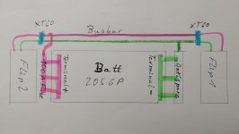
OK, I got it: my batterie is build straight with 6 Cells in parallel and 20 Cells in series. One big 6 by 20 cellspacer.

I will place the antisparc directly on the minus end and the fuse on the plus side.

This will be connected to a 45 cm powerrail (two massiv copper wires) on one side of the batterie with XT90s on both end.

This will keep the cables short, because both powerrails are connected with short 5cm "pigtails" to the fuse and antisparc.

One FLIPSKY is placed on the minus side, the other one on the plus side.

So both FLIPSkYs are directly connected on plus and minus.

I will place the Canbus cable on the other Side of the batterie, far away from the busbar.

Thanks to all, who helped me to prevent expensive mistakes.

What do you think of using two 50A fuses on the plus side near both of the FLIPSKYs instead of one big 100A fuse on the Terminal?

Or maybe 3 fuses?

My plan ist to charge balanced and use no BMS.

Yes, I am aware of the risks, I know I have to monitor the cell voltages manually and have done this for a long time with my DIY modded e-longboard.

But this will be the first time with 72V and 120 Cells.
 
speeed said:
mxlemming said:
[...]

Just run one great big anti spark.

OK, I got it: my batterie is build straight with 6 Cells in parallel and 20 Cells in series. One big 6 by 20 cellspacer.

I will place the antisparc directly on the minus end and the fuse on the plus side.

This will be connected to a 45 cm powerrail (two massiv copper wires) on one side of the batterie with XT90s on both end.

This will keep the cables short, because both powerrails are connected with short 5cm "pigtails" to the fuse and antisparc.

One FLIPSKY is placed on the minus side, the other one on the plus side.

So both FLIPSkYs are directly connected on plus and minus.

I will place the Canbus cable on the other Side of the batterie, far away from the busbar.

Thanks to all, who helped me to prevent expensive mistakes.

What do you think of using two 50A fuses on the plus side near both of the FLIPSKYs instead of one big 100A fuse on the Terminal?

Or maybe 3 fuses?

My plan ist to charge balanced and use no BMS.

Yes, I am aware of the risks, I know I have to monitor the cell voltages manually and have done this for a long time with my DIY modded e-longboard.

But this will be the first time with 72V and 120 Cells.

I'm not sure i understand.

And if i do, this is not a good idea.

Draw a sketch and upload.

Battery... Absolutely nothing except a wire here... Antispark... Busbars... Flipsky x2 in parallel with their grounds permanently connected
 
mxlemming said:
[...]


I'm not sure i understand.

And if i do, this is not a good idea.

Draw a sketch and upload.

This should work. But I am not shure if it will be better to add a 50A fuse on the short plus cables between the XT60s and the FLIPSKYs.

IMG_20211027_213255.jpg
 
The whole point of an anti spark is too slowly deliver power to the caps so it sit on the positive rail allowing the voltage in the caps to slowly rise rather than a short harmful rise that in turn produces the spark we see down line from the direct loading of low resistance caps on a power source with enough volts and amps to cause breakdown of the air around the contact point.

Flipsky switch the positive ev makers do the same why do you feel the negative is an advantage ?

Fets are used to make this connection solid state, tesla have moved from a contactor (relay) based system to solid state not sure if they have put the shunt into it too i suspect they use an igbt or 2 of some sort for the additional power needed.
 
speeed said:
mxlemming said:
[...]


I'm not sure i understand.

And if i do, this is not a good idea.

Draw a sketch and upload.

This should work. But I am not shure if it will be better to add a 50A fuse on the short plus cables between the XT60s and the FLIPSKYs.

IMG_20211027_213255.jpg

This is fine assuming you don't go unplugging the xt60s without turning the Antispark off/disconnecting the can first.

Can't promise you won't kill anything but this should make it much less likely.

Fuses in the positive lines are good anywhere. 100A fuse actually opens nearer 200A which is plenty enough to toast your flipsky.

In fault condition, 100A will toast the flipsky equally well so i guess it doesn't matter, pick based on protecting your battery?
 
The VESC 75V300A project, is using phase shunt, which means the voltages upon shunt resistor will up to the battery voltage. Currently, we are using INA240A1 from TI to do current amplify, its maximum common voltage is -4 to 80V, so for ESC's specs, working voltage beyond 80V is mean less, unless you don't care the risk of damage the INA240A1.
and our Ubox( https://spintend.com/products/75v-100a-single-esc-single-ubox-based-on-vesc )actually have 80V capability, but we still claim it 75V, because we think it need some save zones.
The original VESC FW max voltage limit is 72V, beyond 72V, modify the FW is required.
 

Attachments

  • recommend operating spec.png
    recommend operating spec.png
    25.4 KB · Views: 917
Sorry, but does that project have any relationship to this Flipsky product rated at a max of 84V?

In other words, what was the relevant message you wanted to convey in that post about your 75V limited project?
 
john61ct said:
Sorry, but does that project have any relationship to this Flipsky product rated at a max of 84V?

In other words, what was the relevant message you wanted to convey in that post about your 75V limited project?

Flipsky product max 84v is also based on this project(75v 300A vesc), so what I mean is running 84v or 20s may not be safe enough. as the risk is explained in above.
 
Back
Top