Alright, time to play a little catch up.
TorontoBuilder said:
Yes, IMO for such parts small milled glass fibers are much better than laid sheets. These fibers are used to make epoxy resin for structural fillers and filleting components. They work very very well, but you need to have respirator, gloves and avoid contact with the fibers since they will irritate the skin like crazy.
Thanks, I will try it and see if there is a difference with the fibers. I am certainly familiar working with fiberglass insulation, and the irritation that comes with that. I will definitely wear a respirator, and do it outdoors. its getting chilly though!
TorontoBuilder said:
Additionally, you can add powders to significantly increase the thermal conductivity of the stator. I'm sourcing industrial grade silicon nitride powder to add to the epoxy I will use on my stators.
I know nothing about the additives. I will look into this. I do have concerns about wicking the heat to the exterior of the stator. Obviously that will be close to the magnets. I used N52, which was probably foolish due to the low demagnetization temperature. I wonder if a thermally conductive resin would increase the heating of the magnets.
Jrbe said:
I think a silicone mold would not work out very well if you're clamping it. I'm not sure how much force you're using but ideally you should look at using something that won't deflect much to at all at that pressure. Your clamping deflection will end up your thickness variability. Maybe a .25 - .5" piece of steel or aluminum top and bottom.
I initially agreed with this, but the more I thought about it, the less I am convinced. I was thinking a shell with a thin layer just to help with the mold release.
I was also thinking similarly about the deflection of the shell. I think something rigid like what you suggested is a good idea. I might be able to piece together something
TorontoBuilder said:
A silicone ring could be used with this technique to provide the stator shape. The ring could be made slightly proud of 1/2" and it could compress to the desired dimension, as would the stator windings.
Yeah this is a great idea. This would really simplify things when it comes to having a bit of variation predicting how much it will actually compress. I think it could lead to deflection in the resulting stator, but ideally I think that comes down to how I squish it all down, and the rigidity of the shell of the mold
APL said:
Teflon doesn't stick to anything too,. can be ridged in thicker forms, but comes in thin adhesive backed sheets as well,
maybe good for a liner. Just a thought. (don't ask me how they get adhesive to stick to it)
I haven been thinking about this suggestion a bit. I think I could use something like this in the jig to keep the wires from getting caught on the fins. It would make removing the wire afterwards much easier. Also could be useful in protecting the wires in the event I add laminations to the stator at some point.
APL said:
There are a lot of Hi tech-ish epoxies that will probably fit the bill, but the cost can be very extreme $$$ and usually
need an applicator gun and mixing nozzles as well. Trying to find one that's cheaper and works well involves trial and error,
which in it's self is expensive.
I have a 50mL applicator gun, it works wonders for making the rotors, but I have just been using cheap Scotch Weld DP110 and the high heat Permatex stuff (I cant use that one in the applicator though)
Hummina Shadeeba said:
I bet you could practically fill the whole stator slot if u had a way to crush it in there
This would be the ultimate goal. I understand that the round wire leaves some gaps. This is another reason I opted for the small thickness (32AWG or ~0.2mm) I could probably get away with using thicker wire, It might be actually easier to work with in that it would hold its shape better when crushed together. I've looked into square wire as well. It was certainly more expensive, and I think there's diminishing returns at smaller gauge, as the round wire is more efficiently packed the smaller you go.
Does anyone know if there is some standard to follow for using multi-stranded wire as I am. My understanding is that it helps with losses in high frequency operation, and knowing that I was going to have I high pole count, I went with some pretty thin stuff.
Jrbe said:
There are a bunch of 3D printed motor ideas here. Probably worth a read.
Thanks for the link. I have seen that project, but not that link specifically. That man is very thorough with his work. I might tediously select my magnets the way he did in one of these versions.
Jrbe said:
Also they listed iron filled filament in there for the stator core. https://www.proto-pasta.com/products/magnetic-iron-pla
Yes, this stuff is cool. I actually have a spool of it here. its 13% iron, and wears out your nozzles like theres no tomorrow. I have a hardened steel nozzle, but was not able to get it to work, never figured out why.
Also, I think I am probably not going to go back to 3d printing the stator. I think that the plastic is just too flexible. But it might make okay laminations. Ill hold on to it for down the road.
Jrbe said:
Is that glue sticking well to the plastic?
Yeah its just hot glue, I am only checking back EMF to measure relative differences, its not getting warm at all, and there's only 2 turns per pole.
Jrbe said:
You could also optimize some of your motor parts to bring all of the material in as far as sensible and thin the bolt boss some
Yeah ideally I would love to lose mass and/or overall OD. I think thats where I could reduce inertia the most, if anywhere. Which is part of why I started doing this test in the first place. The stator's end turns currently extend beyond the edge of the magnets. So I would love to know if there is a gain or loss by moving things closer or further by 1mm steps.
The results are in!
Let me preface this by saying that its a little skewed and misleading due to the back iron behind the rotor magnets. The magnets on the ID of the rotor do not have metal going all the way to the edge of them, however the OD does. Also, I'm sure this is something that could be measured with simulations. But I wanted to make something real, and have an excuse to use my scope some more.
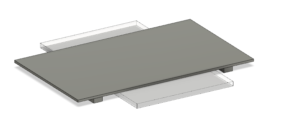
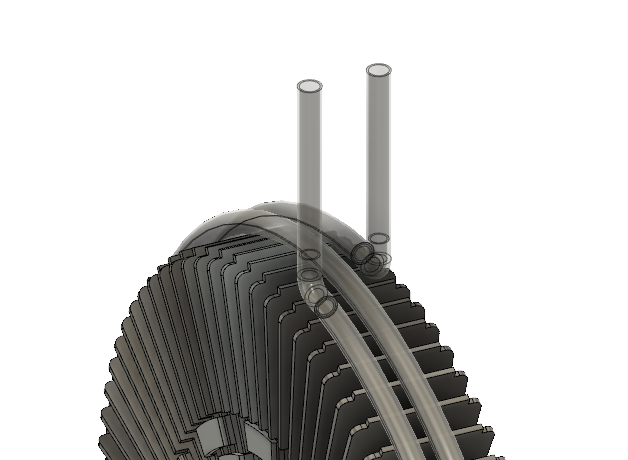
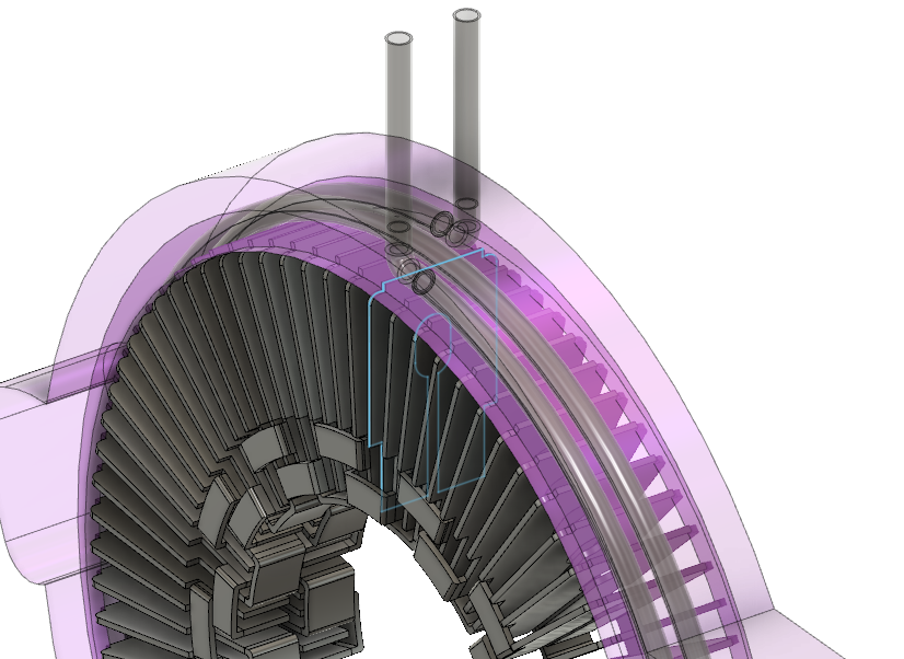
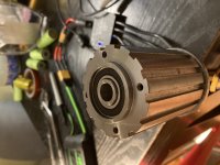
Here's the test setup. I clamped the stator in place, had all the tests labeled and had a machine screw tightened in place on the rotor to spin it with the drill.

This worked well, but I found that test B was giving me weird results on the scope, I'm assuming there was some exposed wire somewhere intermittently shorting things out, but I'm not really sure, I just decided to skip that, and for symmetry I skipped the similar test on the OD.
I used Test A as a baseline which was a 0mm offset from the inner edge of the inner and outer end turn. (all test measurements are peak to peak voltage in mV)
Test A(CH1), C(CH2), D(CH3), E (CH4)

Test A(CH1), H(CH2), G(CH3), F(CH4)


So keeping in mind that the inner diameter is lacking back iron to the edge of the magnets, its easy to understand why it tapers off as you move away from the edge. However, the OD test was a little counter intuitive for me. The voltage was slightly higher when you moved away from the edge of the magnets. My tests only went to 4mm, so I'm curious where the optimal is, but unfortunately this would mean larger OD, more wire, leading to higher overall resistance leading to losses to heat, and just more material and weight.
So the takeaway... I think I need to make better rotors using the new back iron that I got laser cut. which will have back iron to the edge on both the inner and outer diameter, then re-test. But its looking like there is a slight gain, from moving the wire away from the edge of the magnet, but it seems like a negligible increase. and I think quantifiably not worth it due to the other losses incurred.
Measuring heating alone. It might actually be worth it. At reasonable values the loss from heat becomes pretty small, and pushing kV down seems to help keep those values low. This is also not very accurate though, because the temperature would certainly be over 20*C and would climb quickly given the wires were all bundled together and potted in epoxy, obviously increasing resistance, and in a negative feedback loop, contributing to more heat.


Lots to think about here....


")