KT motor controllers -- Flexible OpenSource firmware for BMSBattery S/Kunteng KT motor controllers (0.25kW up to 5kW)

Sorry for my questions but while I am waiting for the 48v 12v step down I try to understand. My goal is to add a torque sensor for a q100h motor, transformed into a mid motor. Currently the engine works perfectly with pas and pswpwer 36 / 48v SVPR control unit and I will use this control unit for tests.
1- the motor works perfectly, once the new firmware has been loaded will there be a need to change the combination of the hall sensors and the phases?
2- in the java tool there is the choice for lcd03, there is no mention of lcd05, does it work with the same choice?
3- I don't know the number of pas magnets of my torque sensor (it is a torque sensor of the cyc motor. Can I go by trial and error? What happens if the number of pas magnets is wrong?
4- throttle min / throttle max. Since the torque sensor is connected to the torque input I guess I have to set the values ​​of my sensor which has a minimum output of 1.5v and a maximum of 3v. It's correct?
5- Battery Current max: my control unit is 20a so I should put 20 * 100/10 = 200?
6- Phase Current max: is it a "dark" parameter for me, do I just leave 500? is this the main culprit for mosfet burns? I don't know how to change mosfets, so I would like to stay safe and not burn anything ...
7- Battery Current cal a: another obscure parameter, since I have a 6 fet control unit I will put 100. Right?
8- Gear ratio: mine is a mid motor, I will not put anything because in any case the speed would be incorrect and I will select the external sensor.
9- Undervoltage: mine is a 48v battery therefore 39v cutoff.
39 * (256/70) = 142. Why 70? Is it the Volt Calib parameter?
10- Overvoltage: 48v battery, then 54.6v max. 54.6 * (256/70) = 200
11- Volt Calib: I leave 69 (but doesn't it have to be 70?)
12 - Gain P and Gain I = I don't know what they are :-( I'll put 0.5 and 1, is that right?
12 - PAS threshold: here too absolute fog ... I don't know the number of magnets in my torque sensor but they are probably either 16 or 32. What should I wear?
13- Assist level 1-5: I leave the default values.
14- morse time 1-3: I leave 50
15- TQ calib: I leave 1500.
16- Ramp end: Duration- Ramp start: I leave 0?
17- hall angle etc: I leave the default values.
18 - Display Type: I have both an lcd3 and an lcd5, so I will try all 2 by checking lcd3
19- Display Type -> Diagnostics: I hope it is not needed because I would not understand anything .... :-(
20- Dynamic Assist Level: using only the torque sensor is it necessary to check?
21- Enable rotor angle correction: my control unit is a VPR, here I understand that it must be enabled.
22 - Bypass PI control regen @low speed: with a mid motor disabled.
23 - Torquesensor: enabled, since I use torque.
24 - Assist Lvl affects throttle: How does it work with a torque sensor? does it mean that the accelerator is limited to the maximum level? If you disable it, does the torque go from 0 to max? so the levels lose their meaning ...
25- Regen Digital: not needed for mid motors without regen.
26 - Speed ​​influences Regen Rate: not needed for a mid motor.
27- Speed ​​influences TQ sensor: enabled, I think ...
28- Power Based Control: disabled, I think ...
29- PAS inverted: does it make sense on a torque sensor?
30- Idle Disables Offroad: disabled
31- External Speed ​​Sensor: enabled for mid motor
32- Switch to 360 degree interpol: disabled
33- High Speed ​​Motor: I think enabled for a q100h motor
Obviously I don't expect to have detailed answers, but if possible to point out gross errors ...
I think answering is useful for other newbies :)
 
andrea_104kg said:
Sorry for my questions but while I am waiting for the 48v 12v step down I try to understand. My goal is to add a torque sensor for a q100h motor, transformed into a mid motor. Currently the engine works perfectly with pas and pswpwer 36 / 48v SVPR control unit and I will use this control unit for tests.
1- the motor works perfectly, once the new firmware has been loaded will there be a need to change the combination of the hall sensors and the phases?
2- in the java tool there is the choice for lcd03, there is no mention of lcd05, does it work with the same choice?
3- I don't know the number of pas magnets of my torque sensor (it is a torque sensor of the cyc motor. Can I go by trial and error? What happens if the number of pas magnets is wrong?
4- throttle min / throttle max. Since the torque sensor is connected to the torque input I guess I have to set the values ​​of my sensor which has a minimum output of 1.5v and a maximum of 3v. It's correct?
5- Battery Current max: my control unit is 20a so I should put 20 * 100/10 = 200?
6- Phase Current max: is it a "dark" parameter for me, do I just leave 500? is this the main culprit for mosfet burns? I don't know how to change mosfets, so I would like to stay safe and not burn anything ...
7- Battery Current cal a: another obscure parameter, since I have a 6 fet control unit I will put 100. Right?
8- Gear ratio: mine is a mid motor, I will not put anything because in any case the speed would be incorrect and I will select the external sensor.
9- Undervoltage: mine is a 48v battery therefore 39v cutoff.
39 * (256/70) = 142. Why 70? Is it the Volt Calib parameter?
10- Overvoltage: 48v battery, then 54.6v max. 54.6 * (256/70) = 200
11- Volt Calib: I leave 69 (but doesn't it have to be 70?)
12 - Gain P and Gain I = I don't know what they are :-( I'll put 0.5 and 1, is that right?
12 - PAS threshold: here too absolute fog ... I don't know the number of magnets in my torque sensor but they are probably either 16 or 32. What should I wear?
13- Assist level 1-5: I leave the default values.
14- morse time 1-3: I leave 50
15- TQ calib: I leave 1500.
16- Ramp end: Duration- Ramp start: I leave 0?
17- hall angle etc: I leave the default values.
18 - Display Type: I have both an lcd3 and an lcd5, so I will try all 2 by checking lcd3
19- Display Type -> Diagnostics: I hope it is not needed because I would not understand anything .... :-(
20- Dynamic Assist Level: using only the torque sensor is it necessary to check?
21- Enable rotor angle correction: my control unit is a VPR, here I understand that it must be enabled.
22 - Bypass PI control regen @low speed: with a mid motor disabled.
23 - Torquesensor: enabled, since I use torque.
24 - Assist Lvl affects throttle: How does it work with a torque sensor? does it mean that the accelerator is limited to the maximum level? If you disable it, does the torque go from 0 to max? so the levels lose their meaning ...
25- Regen Digital: not needed for mid motors without regen.
26 - Speed ​​influences Regen Rate: not needed for a mid motor.
27- Speed ​​influences TQ sensor: enabled, I think ...
28- Power Based Control: disabled, I think ...
29- PAS inverted: does it make sense on a torque sensor?
30- Idle Disables Offroad: disabled
31- External Speed ​​Sensor: enabled for mid motor
32- Switch to 360 degree interpol: disabled
33- High Speed ​​Motor: I think enabled for a q100h motor
Obviously I don't expect to have detailed answers, but if possible to point out gross errors ...
I think answering is useful for other newbies :)

Hi,
I'm planning to put a few touches on the wiki so that the parameters are easier to understand, so this is just a quick writeup:
1) Usually the only thing needed is adjusting motor angle. I recommend the BluOSEC app for this purpose - and initial setup, as you can see the correction angle, as well as phase B current for smaller adjustments. Once you're happy with the calibration, then LCD3 can be used instead.
2) AFAIK they share the same protocol, but maybe someone else can confirm. I also have LCD04, but haven't tested it with OSEC yet.
3) If it's wrong, then assist by cadence is calculated wrong. I never tested it however.
4) Again, this is where BluOSEC gets useful, you can finetune your throttle thresholds perfectly without worrying too much about converting ADC values to real voltage levels.
5) Yes, maybe 19A to be safe
6) Phase current is basically battery current with varying dutycycle, more means faster acceleration. I prefer to stay at 30A for anything with nylon gears, to reduce wear.
7) Again, I'd recommend calibrating with BluOSEC
8) Yep
9) Good rule here is 2.7V times number of cells. 2.8V discharge threshold is safe under load.
10) Overvoltage should be set higher than max battery voltage, usually 4.3 times number of cells
11) Guessed it, BluOSEC
12) AFAIK, there is no guide for those. You can try 0.1/0.4 and see if the acceleration isn't too slow for you. At some point, the controller will start oscillating, which you'd see on setPoint (duty cycle) vs. battery current
24) I think it doesn't apply for real torquesensor operation. Once torquesensor is on, it had no effect for me.
29) Depending on individual motor
33) High speed commutation was kinda buggy when I tested it. I use 15kHz with 5:1 geared hub and it's perfectly fine beyond 400rpm.
 
many thanks for your kind reply.
Since the control units are many but not infinite, in particular the control units with 6 mosfets are relatively few, it would be useful to have a database of working settings. Unfortunately I have been reading for days and honestly it is a bit depressing :-( there are tons of problems and very few reports of working systems. I can't figure out how many actually get a usable system every day :-(
 
[/quote]

3. By measuring the voltage on the throttle at min and max position and then:
Throttle_min=voltage_min/5*255
Throttle_max=voltage_max/5*255

[/quote]
i tried this formula for throttle min/ max but i have a problem.
my torque sensor have a min voltage of 1,5v

1,5/5*255 = 0.0011764705

??
idem for max voltage, in my torque sensor 3v

3/5*255 = 0.0023529411

??

i don't understand, i put 117 and 235?
 
i don't understand, i put 117 and 235?

...you're doing the maths in the wrong order, try,

(min/5) x 255,
and
(max/5) x 255,

....then all will make sense.
:)
 
geofft said:
i don't understand, i put 117 and 235?

...you're doing the maths in the wrong order, try,

(min/5) x 255,
and
(max/5) x 255,

....then all will make sense.
:)

It's a while since I played with this stuff, but from memory I *think* the 'Throttle min' and 'Throttle max' in the configurator only apply to throttle even when 'Torquesensor' option is selected.

I think you'll need to alter these numbers in ACAcontrollerState.C to set up the tqsr min/max....

uint16_t ui16_X4_min_range = 500;
uint16_t ui16_X4_max_range = 900;

.....I can't remember how these numbers are calculated but I think I (using trial and error) I ended up with something like 300/700 (not 500/900).
Just be aware you may have to play with these to get things working correctly.

EDIT: I've just remembered that I'm using the 'Torque from X4' branch, the above info may not be relevant if you're using torquesensor only (i.e. without throttle) in the Master branch.
 
I have recently used both branches and torque from x4 is highly superior to the standard branch. It's just much more stable. Otherwise they are very similar :)
 
andrea_104kg said:
thanks! I also think to use x4 version for torque sensor. What's your controller?

You'll see my setup in the bottom line of the signature at the very bottom of my posts.

I run the 6-fet up to around 18 amps without any problems. It all runs very sweetly, the only downside of the OS firmware is that it runs the controller a little hotter than the stock version, mine is mounted under the rear saddlebag in the airflow and stays cool.

As Vbruun states, the 'Torque from X4' branch doesn't suffer from the occasional processor overloads that were happening with the Master branch.
 
How do you recognize a processor overload when riding ? Can it be dangerous ?

If my setup (torque simulation, throttle only) is working fine on master branch, can I switch to Torque from x4 branch without any changes ?
 
jm1090 said:
How do you recognize a processor overload when riding ? Can it be dangerous ?

If my setup (torque simulation, throttle only) is working fine on master branch, can I switch to Torque from x4 branch without any changes ?

In my case it behaved almost as if the battery had momentarily disconnected, the power assist would stop, then a second or two later the display and the motor restarted. Annoying but not particularly dangerous I would say.

I think I remember Stancecoke saying that the optimizations in the code to prevent this were only added to the torquesensor section in the 'torque from X4 branch', so there would be no point in updating if you're not using a torquesensor.
 
geofft said:
jm1090 said:
How do you recognize a processor overload when riding ? Can it be dangerous ?

If my setup (torque simulation, throttle only) is working fine on master branch, can I switch to Torque from x4 branch without any changes ?

In my case it behaved almost as if the battery had momentarily disconnected, the power assist would stop, then a second or two later the display and the motor restarted. Annoying but not particularly dangerous I would say.

I think I remember Stancecoke saying that the optimizations in the code to prevent this were only added to the torquesensor section in the 'torque from X4 branch', so there would be no point in updating if you're not using a torquesensor.
Yes I just checked it and the computation for the torque sensor is more efficient. So the torque_from_x4 branch is probably only intended for people that use torque sensors.
 
iaval said:
jm1090 said:
iaval said:
jm1090 said:
- I am currently modifying the controller with 100V caps and mosfets in order to run at 23s li-ion (not fully charged, probably around 90V max). I have cut the metal case in order to solder MLCCs between the + and - buses, along the whole buses (about 50 MLCC, 500 µF total). I hope this will save my mosfets from voltage spikes when I will run 90V and 200A phase :)

Don't forget to replace ADC resistors so that you won't get overvoltage related issues :thumb:

https://endless-sphere.com/forums/viewtopic.php?f=30&t=87870&start=4475#p1661100

Oh yeah, would have definitely missed that, thank you :)
Thanks for the writeup :bigthumb:
I'm not at my test rig, but I'll give it a spin later.
Two questions tho - would it be difficult to modify it so that it disengages once pedalling stops (no PAS input), as well as the first two conditions (brake+throttle position change)?

And also have you noticed any throttle lag with DD motor?

I don't have throttle lag once I am running. Maybe only a little at startup.. ?

For PAS input to disable cruise, I need to take a look at the code and see if it's easy to do, but I don't have PAS to test it, you would need to be beta tester :D
 
Merry Christmas to all!
I won't leave you alone even at Christmas ... :)
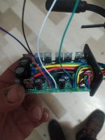
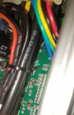
I opened the control unit, soldered the wires, (including x4) programmed with st32, all ok.
rotto1.jpg
rotto2.jpg
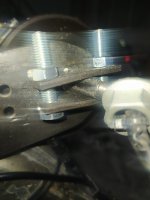
however, when I mounted it on the bicycle, everything starts at maximum speed, the level regulator is irrelevant. The force is so great that it made my mid motor shaft spin, and it was tight! The wires went short and smoke came out of the motor :-(
rotto3.jpg
Now I'm continuing the experimentation with a hub. The control unit has not burned out, the hub motor runs but how the mid motor unit starts at maximum speed ... where am I wrong?
I tried to measure the voltage on the x4 port, I have 1.7v at rest and 1.9v if I move the pedals (on the stand) so minimum variation, I don't think the motor starts at maximum due to the sensor ...
 
andrea_104kg said:
where am I wrong?

Some Kuntengs have a pull up resistor on x4 to attach a temperature sensor. So you can check that easily by measuring the voltage on x4 with no throttle connected. It should be zero.
If it's 5V you have to remove the pull up or solder an additional pull down of about 1k to x4 and GND.

Merry Christmas!

regards
stancecoke
 
Thanks so much! In fact I measured and on pin x4 there are 5v :-(
The engine starts at maximum even with pin x4 detached from the torque sensor!
But I think this depends on the fact that on x4 there are 5v ... can I put an external resistor, without opening the control unit again, by connecting wire x4 to any negative?
This is because I can't really identify the internal resistance to be removed ...
 
ok, I tried to put a trimmer between the wire coming out of x4 and the ground. The voltage drops to zero. The engine does not start anymore. Then I measure the voltage at the output of the torque sensor and correctly I find 1,5v.
But when I connect the white wire of the torsometer to x4 (which I remember is connected to ground) the voltage drops from 1.5v to 0.2 volts and obviously the engine does not start. What am I doing wrong?
 
andrea_104kg said:
What am I doing wrong?

The safest is to find and remove the pull up in the controller.
If you work with an additional pulldown you have to find a value, that pulls the voltage down enough, but let the torquesensor pull the X4 pin up. I guess the torquesensor output can't deliver much current, to keep the output on the wanted level, your pull down pulls it down 😄

regards
stancecoke
 
but how to identify the right resistance to remove?
if i connect the torsometer to the throttle port instead of x4 will it work? what is the difference? I specify that I do not use accelerator .
 
andrea_104kg said:
but how to identify the right resistance to remove?
if i connect the torsometer to the throttle port instead of x4 will it work? what is the difference? I specify that I do not use accelerator .

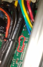
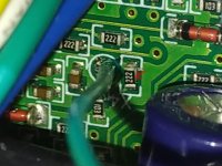
You could connect it on the throttle line probably but the code would need to be changed. On x4 you will also get more resolution I think. It is not hard to identify the resistor to remove (see images).
20211226_173449.jpg
20211226_173406.jpg
 
ok thanks for the image. I removed the pull up, it's not easy it's really small! 20211226101203.jpg20214926104959.jpg

now on x4 i have only the volts of torque sensor :D
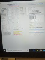
but i tried and (on stand) the motor start as a rocket after a little pressure on bicycle pedals, a tenth of a turn is enough. the speed is incredible, I have not tried it on the road but I think it is a maximum start .... I am attaching my schedule, if by chance something is wrong ...
IMG_20211225_174807.jpg

I think that the immediate starting effect is due to the pas and not to the torque sensor because I measured the sensor tension, empty 1.47v, turning the pedals by hand it rises very little to 1.6v ..
Is it normal with the bike on the stand a rocket start turning the pads very little?
 
now on x4 i have only the volts of torque sensor :D
but i tried and (on stand) the motor start as a rocket after a little pressure on bicycle pedals, a tenth of a turn is enough. the speed is incredible, I have not tried it on the road but I think it is a maximum start .... I am attaching my schedule, if by chance something is wrong ...

...when I switched to the 'Torque from X4' branch I found the torquesensor was massively over-assisting and I had to reduce the configurator values considerably to get a sensible level of assist, (TQ calib down to 70, assist levels 1-5 all below 50%).

I never really figured out why it was necessary to do this, but at those numbers it works pretty much perfectly, so be aware you may have to do something similar.... :?
 
today I tried the bike, without changing the initial setting. As I thought the bicycle is undriveable, it starts at 1160w! It is not possible to perceive any functioning of the torque sensor because the bike is immediately at maximum, regardless of level. How is it possible that a 20a control unit, set at 19a, reaches over 1100w I don't know, but I fear that the mosfets will last very little ... Tomorrow I will try to cut the values. If anyone has any other ideas ...
The software is set for external speed sensor, but for now I have not put it, can it affect? I don't think so because the speed is still very low, it starts at max from a standstill
 
Back
Top