New "TSDZ2 Torque Sensor Central Motor"

ornias said:
LeftCoastNurd said:
when dealing with an inductive circuit (eg, the motor coils), you really need some margins between peak rated voltage and operating voltage, something like 25% at a bare minimum
.

It's also not really an answer either, as I was refering to the possible (side) effects. Not "rules of thumbs". I think i'm smart enough to understand that something rated for 48v is not supposed(!) to run at anything much higher than that.

On the other hand the 36v coil also runs quite decent at 48v, so it's not support clear what the actual coil ratings actually are in this case, as we also dont get any certification reports. Besides the point that they are 250w nominal rated, using an older measuring method (which is also the reason they are actually closer to 500w nominal).

It’s not the voltage rating of the coil that was being referred to. In simple terms inductive circuits can increase the voltage beyond that with which they are supplied, potentially taking other parts of the circuit beyond their ratings. Hence giving a safety margin.
 
Good morning everyone, I have not written in the forum for a long time because until now my tsdz2 worked with 0.16 for kt3 lcd without any problem. I have decided to switch to a more modern software but I can't find anything for this screen. can someone help me locate it?
thank you.
sorry for my bad English
 
Elinx said:
You can consider to use a 1500W step up boost converter, that can give a relative high current.
In that case you can keep the output 36V or 48V, independent of the lower input Voltage.

casainho said:
-Pete- said:
Hi, firstly thanks to all the developers and contributors to the TSDZ2 OSF, much appreciated! I've just fitted a 36V TSDZ2 with a VLCD5, and bought a Malectrics Arduino spot welder to make my own packs from new cells. Now I'm trying to consider ALL the possibilities, and I read that the lowest voltage is 24V but wondered if it's possible to go lower? 6S would be 19-24V and physically small, I can get build 5 mile packs for about £40 each using decent new cells and 6S balance chargers are cheap. Any thoughts?
You need to test by yourself the lowest battery voltage possible on the motor controller.

You will also get lower cadence, is up to you to test and see if you like the results.
Thanks. I've installed emmebrusa 1-20.1C-2.1 which is great with a 10S pack, I'm going to try 6S 7S and 8S.

I've read the EN manual but don't understand how to set parameters on the display. I can get to E02/3/4 flashing but then don't know how to change the values - is there a button which toggles between all the available choices? I need an 'idiots guide' please :)

Say, for example, that I want to select Cadence Assist. From power-up, exactly what buttons do I need to press, for how long, to do this? The manual says "The "Set parameters" function is enabled/disabled at level 0-OFF by setting E02 - SET PARAMETER, lights button twice (on/off) until E02 flashing." so must I do this first?

Also, some feedback, I've tried MPH vs Km/H and understand the x5/8 conversion, I don't like full battery saying 62.4% but also don't want the battery voltage to be x1.6. Could you change the next release so I can have MPH, 99.9% battery when full and accurate battery voltage?

Thanks.
 
-Pete- said:
..... don't understand how to set parameters on the display. .... I need an 'idiots guide' please :)
..... I want to select Cadence Assist. From power-up, exactly what buttons do I need to press, for how long, to do this?...

-Pete- said:
... I've tried MPH vs Km/H and understand the x5/8 conversion, I don't like full battery saying 62.4% ....

I have moved these questions and answers to here, because imho that is a better place for it.
 
I have a problem with my new 860 display,

When I flash with 860C_v20.1C.3-bootloader, it will not boot up, but when I`m flashing with 860C-display-OSF_v1.1.0-for-bootloader then it boot up....

Somebody know what I can do or what is wrong ?

Display is marked on the back side with:
860C GD3V160 XF1.0
V5.2 202105130021
 
Hello everyone. I haven't posted in awhile because everything was working more or less to my satisfaction.

I have the 52V OpenSource EBike 860c version 1.1.0

Today I encountered a new situation. Mid ride the system cut out. No power, 860c display turned off. When I tried to restart, I got a very brief flicker, but then nothing. The battery was fully charged and I have set low battery cut-off appropriate to my 52 volt battery.

So there are two odd things happening (but not necessarily related):
1. The 860c power cut off (a brief flicker when I try to turn it on; then nothing).
2. My multi meters tell me the battery has +/- 46V but my charger thinks the battery is full and will not activate to charge. After writing this, I noticed that the charger is reading 57.7 V even with no battery plugged in. I guess it could be a charger issue.

Batter is 52V 30AMP 6AH SAMSUNG 30Q LITHIUM MINI-CUBE E-BIKE BATTERY from Electrify Bike Co.
Charger is 52v Advanced 300w Eco Charger - 1 to 5A - 80/90/100 - from Eco-Cycles

After writing this I noticed that the charger is reading 57.7 V and the charge light is green with NOTHING plugged in. So I guess there is something wrong with the charger. The charger is less than a year old. Anyone had this issue?
 
After writing this I noticed that the charger is reading 57.7 V and the charge light is green with NOTHING plugged in. So I guess there is something wrong with the charger. The charger is less than a year old. Anyone had this issue?

Sorry...long day. Riding the bike with no charge adds a little resistance; drained the blood from my brain :D
 
I have a problem with my new 860 display,

When I flash with 860C_v20.1C.3-bootloader, it will not boot up, but when I`m flashing with 860C-display-OSF_v1.1.0-for-bootloader then it boot up....

Somebody know what I can do or what is wrong ?

Display is marked on the back side with:
860C GD3V160 XF1.0
V5.2 202105130021
 
I have bought new TNDZ2 (throotle version) and 860 display and flashed both with newest firmware TSDZ2-v20.1C.3-860C-NEW.hex and 860C_v20.1C.3-bootloader.bin.

The display boot up fine when I have it connected to the bootloader box, but not the TSDZ2 controller....

I have double checked my wiring between the display and TSDZ2 against these guide:
https://github.com/OpenSourceEBike/TSDZ2_wiki/wiki/Wire-860C-850C-to-TSDZ2

And have found no mistake.

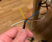
I have mesured the cables from the TSDZ2 try to understand these.
Between:
Black - Brown = 0,1v
Black - Orange = 0v
Black - White = 0
Black - Yellow = 0
Black - Red = 0v
Black - Blue = 0v
Black - Green = 0v

And then I check against red....
Red - Brown = 1,5v
Red - Orange = 0v
Red - White = 3,8v
Red - Yellow = 1,7v
Red - Black = 0v
Red - Blue = 50v
Red - Green = 0v

These make me confused compared to the guide.... is not black ground ? is red ground ?

How can I figure out what is what when it comes to the cable from TSDZ2 ? the cable to 860 display I have control over,
they was verified when I flashed the display....


Thank you all ! :)
 

Attachments

  • 01.JPG
    01.JPG
    30.7 KB · Views: 1,219
gordone said:
....
I have double checked my wiring between the display and TSDZ2 against these guide:
https://github.com/OpenSourceEBike/TSDZ2_wiki/wiki/Wire-860C-850C-to-TSDZ2
...
Read & look carefully, ignore the mention of colors and concentrate at the circles on the pin's of the two pictures to connect the right pin's
 
Wapous said:
casainho said:
Wapous said:
casainho said:
It is your design? If so, can you share the source files? because I am pretty sure they can be very useful for others.

And I wish some mechanical guy could improve the motor by reducing the noise - I think the noise comes from the gears, maybe from the main gear and the pinion gear.


I did industrial design for several years. I have been using Solidworks software since 2000.
Obviously I would be happy to offer the reverse engineering drawings free of charge but NOT in the native form.
Those interested only have to ask for the desired format.
Like STEP, DXF, SAT, IGES etc.
Note: The CAD files you see in my mail are not for production but for viewing. But these CAD drawings are faithful to the components of the TSDZ2 engine.
Can you please please share in STEP files as also that images, so I can add to our github and to the TSDZ2 FAQ repair page?
I am sending a step file of an assembly. If you want individual files let me know. Witch program are you using to open the step files?
https://drive.google.com/file/d/1QTW4yIUq8taKDaHIc0sHz9c2OhApSDFv/view?usp=sharing
Animations will follow soon.

Wapous, does your Solidworks CAD file have the motor cover and body included? I imported it into Fusion 360 and and it has the internal components with pedal cranks. Really great work you have done with this!
 
Wapous said:
Wapous, does your Solidworks CAD file have the motor cover and body included? I imported it into Fusion 360 and and it has the internal components with pedal cranks. Really great work you have done with this!
New step assembly with covers. Note: The main helical gear teeth are conform and can be used for production. All other parts are for illustration purpose only. Around 450 meg.

https://drive.google.com/file/d/1HMBWYkCMDfA5ea43-4bcd3PIKebm9_Ln/view?usp=sharing

Wapous, thanks for sharing! This is really great work. Imported perfectly
 
Hello,.
I have a manufactured bike with a tsdz2 36v included. I tried multiple times to flash through the explained process but always get device not detected.

The difference is that that the speed sensor is a 6 pin but not the usual wires. It's more like Julet cable with 6 colors ( black, red , yellow, white , green & blue).

As anyone experienced this and could advice how to detect SWIM GND & VCC wires ? Thanks
 
lolo2905 said:
...
I have a manufactured bike with a tsdz2 36v included. I tried multiple times to flash through the explained process but always get device not detected......
I don't exact understand what you describe with these colors, because normally you only need the to unplug the connector.
imho there should be no problem to connect the STlink wires directly to the Tsdz2 speed plug.

I don't know were you have bought this Tsdz2, but if it is from Enerprof Germany, then you have for sure a new controller version, which can't be flashed with STlink.
Also the current version of osf is not suitable either.
 
About TSDZ2 firmware on the new V2 motor controller

I am being developing, testing and learning FOC motor controller. I am using the EScooter M365 because there is high interest on it, because like TSDZ2, it is a really cheap option. The motor controller is cheap as the TSDZ2 one, and widely available.

Unfortunately, the TSDZ2 V1 and V2 microcontrollers are inferior and so this FOC motor controller code can not be directly reused. However, there are parts that could be reused and I am pretty sure would improve current OpenSource firmware, like the angle estimation using the PLL. And on TSDZ2 V2 motor controller, probably the FOC code could be adapted and be much more improved.

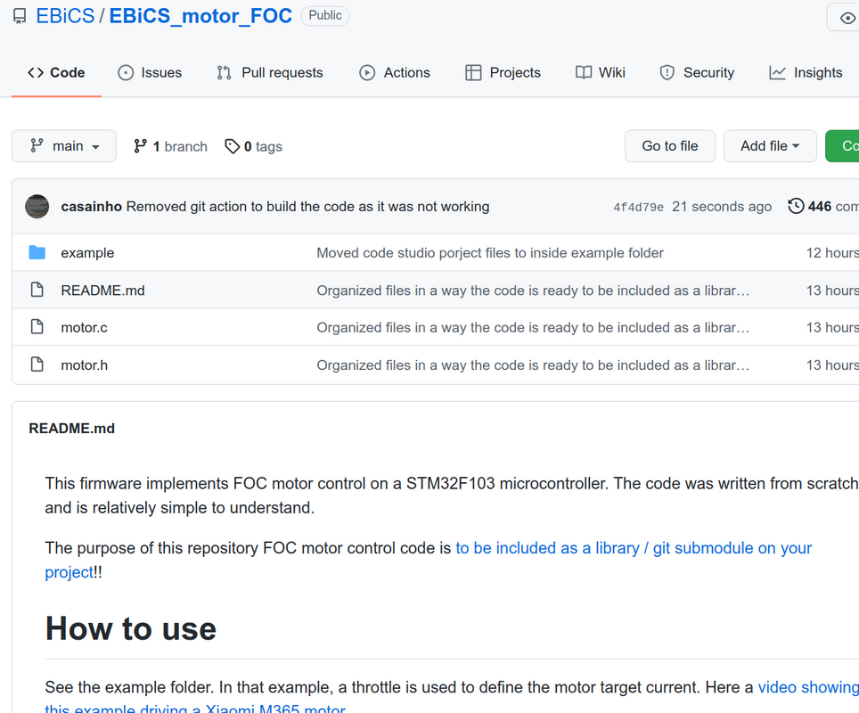
But to do all this, it is need time!! Or at least more developers whiling to do it. What I did strategically was to make a FOC motor control code (based on EBICS firmware) as a library / git submodule to be included on different projects, so developers can reuse this piece of technology and saving time: https://github.com/EBiCS/EBiCS_motor_FOC


So I hope this code can be reused by other developers and get more traction, and who knows, help the TSDZ2 OpenSource firmware developers!! (can be me in future, if I have time to revise the current TSDZ2 motor firmware).

By the way, I am also working on our DIY, customizable, easy to to build and repair motor controller, running our OpenSource firmware. I am always asking to myself: should I focus on developing the firmware for TSDZ2 new V2 motor controller or try to exchange that motor controller by my own DIY motor controller, that already has good performance??

Here is our very first prototype, running our FOC firmware, driving a M365 motor:
[youtube]NelnB91Vqgw[/youtube]
 
Dang. Went to get on my bike today (TSDZ2 with open source kt-lcd3) and the temps are instantly saying they are over 100C jumping around..
Is this likely water in the LCD or the motor housing? i have opened the motor housing and the wires around the temp sensor all look dry so im a bit confused what's going on. Was definitely wet last time i went out and i hosed the bike down, as ive done many times before, but never had this issue..

Have stripped down the bike and bought motor and screen indoors to dry out in the warm so hopefully any water inside dries out.

Has anyone had this issue before?
 
casainho said:
About TSDZ2 firmware on the new V2 motor controller

I am being developing, testing and learning FOC motor controller. I am using the EScooter M365 because there is high interest on it, because like TSDZ2, it is a really cheap option. The motor controller is cheap as the TSDZ2 one, and widely available.

Unfortunately, the TSDZ2 V1 and V2 microcontrollers are inferior and so this FOC motor controller code can not be directly reused. However, there are parts that could be reused and I am pretty sure would improve current OpenSource firmware, like the angle estimation using the PLL. And on TSDZ2 V2 motor controller, probably the FOC code could be adapted and be much more improved.

But to do all this, it is need time!! Or at least more developers whiling to do it. What I did strategically was to make a FOC motor control code (based on EBICS firmware) as a library / git submodule to be included on different projects, so developers can reuse this piece of technology and saving time: https://github.com/EBiCS/EBiCS_motor_FOC


So I hope this code can be reused by other developers and get more traction, and who knows, help the TSDZ2 OpenSource firmware developers!! (can be me in future, if I have time to revise the current TSDZ2 motor firmware).
Today I connected TSDZ2 motor to Xiaomi M365 motor controller running our OpenSource firmware. I can tell you that the motor noise and vibrations are very low, I never saw it running so good. On the lab power supply I can see the current it uses and it is also a low value as expected:

[youtube]ueGZx3Urf0c[/youtube]
 
I have an issue with my TSDZ2 that I don't understand. I left it outside on a cold and wet night (0C 100% humid and rainy), I normally leave it inside at night. The next morning it didn't even turn on, the controller shorted, and I had a spare at work, replaced the controller and it turns on again.

But now the torque sensor does not seem to react, the walking function still works so my new controller works. What can I do to get the torque sensor working again? Not running the open-source FW, the install seems to hard for a newb like me.
 
Malloot said:
.... What can I do to get the torque sensor working again? Not running the open-source FW,.....
If you have a vlcd5 with stock FW, you can check with the hidden menu the TE and TE1 values of the torque sensor for zero and max weight. Check this first to determine if the torque sensor is the cause.
When you see different values it will be another sensor (PAS or speed)
 
Back
Top