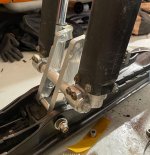
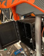
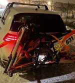
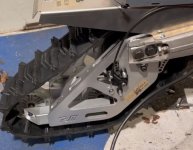
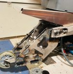
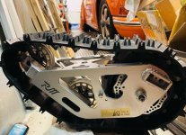
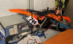
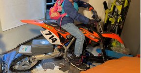
Just started a small new project before the Christmas holidays. It will be a small snow moped. Got so inspired when I stumbled across Moonbikes  on the internet. (google it, a light snow vehicle with hub drive) Then I just found a empty dirt bike frame cheaply on an ad, a 2013 KTM 85. No wheels or motor, perfect for my build. I bought an used ski from a snowmobile and mounted to the front. I also have an electric boat motor conversion, I wanted to use that same 48v battery, so I made a box in the original motor position.
on the internet. (google it, a light snow vehicle with hub drive) Then I just found a empty dirt bike frame cheaply on an ad, a 2013 KTM 85. No wheels or motor, perfect for my build. I bought an used ski from a snowmobile and mounted to the front. I also have an electric boat motor conversion, I wanted to use that same 48v battery, so I made a box in the original motor position.