
If you can actually test the efficiency of the NuVinci, I'd really like to know how much power it wastes. Assuming I ever have money to spend on stuff again, I'd like to put one in my drivetrain (not in the wheel itself) to replace all the derailers and stuff. If it's not all that efficient, I might just build my belt-CVT I've been working out instead.
You are using an out of date browser. It may not display this or other websites correctly.
You should upgrade or use an alternative browser.
You should upgrade or use an alternative browser.
Y-pedal's two stage RC drive..........
- Thread starter recumpence
- Start date
recumpence
1 GW
Ypedal said:easy peazy..
Oh, my goodness, you would get along great with my 6 year old. :wink:
(In manor of speaking, not building
Matt
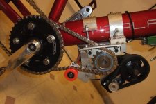
Front chain tensioner also needed to be spring loaded as my sprokets are not perfectly centered this makes a tight/loose/tight/loose chain problem, cut a piece of aluminum, nylock nut, bag of springs i picked up a while ago came in handy .. ( my neighbor's wife scoffed at me when i picked up this bag of springs, " wtf are you going to do with that now.. " .. ! HA ! )
Attachments
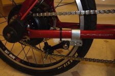
And the rear, this is going to need some beefing up, it held up for a while during my test ride but the chain went off the guide wheel..
Having both tensioners spring loaded made a huge difference in the system smoothness factor, no more tight spots in the crank rotation ! 8)
No load now at 300w ! ( from 400w before )
With rear brakes ( needs caliper ) and frame mounted LiPo ( am thinking 20ah min. ) this rig will be a wheelie machine !
Bottom line, the lower gearing helps a great deal !!!! alot better throttle range and the power spikes to 96 amps when you snap the throttle then settles down quickly as the motor rev's up fast.. it's dark outside and daaaaamn cold so the test was short..
Next step, playing around with the CC setings...
Attachments
johnrobholmes
10 MW
Could you tension the chain towards the frame to get more chain wrap on the sprockets? It would decrease the load on each tooth.
recumpence
1 GW
Sounds good.
I cannot wait to see what your efficiency looks like.
I love watching other people put HUGE time into a build. I can just sit here and let you do all the work. :wink:
Matt
I cannot wait to see what your efficiency looks like.
I love watching other people put HUGE time into a build. I can just sit here and let you do all the work. :wink:
Matt
oatnet
1 MW
Ypedal said:Another issue to sort out is the Cycle Analyst, i'm currently using an inline model with the original shunt, they are ok for X5's at 50 amps but this thing needs juice and lots of it so i need to beef up the shunt...
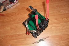
Got this beauty with my Agni 95 Reinforced motor and curtis controller, ( Thank you Bikeraider !!! ) rated at 500 amps ! I have no clue how to wire this up yet but it's on the list for this weekend !
Going to either double Anderson PP45's or the bigger PP75, single run of 10 gauge from the backpack is not adequate..
If you haven't tackled this yet, maybe I can save you some research time. When you cut the cable of your shunt-based CA, you will find the same (4) wires (Orange/Orange-white/Blue/Blue-white) used by the high-current CA, and you can use the diagram below to wire it.
To get accurate readings you would want to set the rShunt value in the advanced menu of the CycleAnalyst. Assuming this is a 500A 50mV shunt like I used on the VW Bus, Justin told me: "For a 500A 50mV shunt, you would want to set the RShunt value in the high range mode to 0.1000 mOhm". The standard CA is only good up to 100v, beyond that you need the CA-HC High current model.
Rather than terminating the CA wires directly to the shunt, I would recommend putting a connector in the middle, and if you use a standard CA connector you can use the shunt on any 6-wire Cycleanalyst too. I cut the wires on my Shunt-base CA so I could run them through the channels in TidalForce frames (too small for the actual shunt) and wired a standard 6-wire CycleAnalyst connector between them. Now I can plug the original CA shunt to any Direct-connect CA (CA-DP/DPS), set the rShunt value to 1.399, and viola the 6-wire CA is converted to a inline shunt CA. I can also use my inline shunt CA on any direct-connect controller.
Here is a wiring guide for connecting a shunt to a CA connector, I have a 80-90 CA connectors left if you need some.
CA connector <--> Shunt Wiring
1) Vbatt (red) <--> Orange
2) D gnd (black) <--> Blue-Striped
3) A gnd (blue) <--> Blue
4) Isense (white) <--> Orange Striped
5) Hall (yellow) <--> NULL
6) Ebrake (green) <--> NULL
-JD
karma
10 kW
Ypedal said:And the rear, this is going to need some beefing up, it held up for a while during my test ride but the chain went off the guide wheel..
Having both tensioners spring loaded made a huge difference in the system smoothness factor, no more tight spots in the crank rotation ! 8)
No load now at 300w ! ( from 400w before )
With rear brakes ( needs caliper ) and frame mounted LiPo ( am thinking 20ah min. ) this rig will be a wheelie machine !
Bottom line, the lower gearing helps a great deal !!!! alot better throttle range and the power spikes to 96 amps when you snap the throttle then settles down quickly as the motor rev's up fast.. it's dark outside and daaaaamn cold so the test was short..
Next step, playing around with the CC setings...
ypedal im looking for a chain tensioner did you make that one or did you buy it? :wink:
MitchJi
10 MW
Hi Y,
!
Probably stating the obvious but if you increased the reduction in stage one and two rather than stage four it would improve rather than worsen the pedaling range.Ypedal said:Also going from a 48t to a 40t chainring to the rear wheel.. That should gear me down a good bit.... makes pedaling gear range even further out of wack.. but hell, not as if i plan to pedal at 50 clicks !
Can you get better chain alignment?Ypedal said:And the rear, this is going to need some beefing up, it held up for a while during my test ride but the chain went off the guide wheel..
Happy to hear you are getting it dialed inYpedal said:Bottom line, the lower gearing helps a great deal !!!! a lot better throttle range and the power spikes to 96 amps when you snap the throttle then settles down quickly as the motor rev's up fast..
!JRH : The 40t chainring brings the chain too close to the fraim to tension " up " .. i have to pull down to avoid the frame.. but it's a 22t rear ENO, enough teeth to keep things hooking up. :wink:
Oatnet : Thanks man !!!
Karma : Jimmy rigged it from a leftover chaintensioner that broke and now only locks on the reverse way ( spring broke inside, but hooks somehow enought to work !! .. the mount is from a household ceiling fixture i used for my battery discharger.. thin metal, will need to replace with thick aluminum )
Mitch: I agree, gear changes on the RC side would keep the pedal action suitable, but with 12S lipo i think i'm going to have to change the 45t 2nd stage gear to a 60t matt has on hand, right now i just want to ride and make due with parts i have on hand right now, beats waiting for shipping stuff across countries..
Chainline is not perfect on stages 3 and 4, but it's in the ballpark, once the snow starts to fall i'll take it all apart and re-do it all proper 8)
http://www.allelectronics.com/make-a-store/item/SNT-200/200-AMP-SHUNT-50MV-200-AMPS/-/1.html
Ordered 2 of the 200amp and 2 of the 100 amp shunts, the one 500amp i have now is way overkill ( but mainly too freakin heavy !! ) i'm hoping the 200 amp is half the weight.
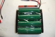
A few days ago i decided to re-built a 24v pack of PSI cells i got from a guy in Japan, this pack is originally form Cyclone Taiwan, assembled with shipping tape !!! .. yikes..
For the Castle controller, the BMS has to go.. and this pack will allow me to keep my existing 48v pack in a backpack intact so i can run 2 of the high-powered ebikes at the same time ! ( Video chase bike ! )
Ordered 2 of the 200amp and 2 of the 100 amp shunts, the one 500amp i have now is way overkill ( but mainly too freakin heavy !! ) i'm hoping the 200 amp is half the weight.
A few days ago i decided to re-built a 24v pack of PSI cells i got from a guy in Japan, this pack is originally form Cyclone Taiwan, assembled with shipping tape !!! .. yikes..
For the Castle controller, the BMS has to go.. and this pack will allow me to keep my existing 48v pack in a backpack intact so i can run 2 of the high-powered ebikes at the same time ! ( Video chase bike ! )
Attachments
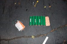
So i start to cut the tape, remove nuts, remove copper bus bars, 2 cells removed and 6 to go.. but as more tape gets cut, i have BMS wires dangling around, and the cells are like wet noodles in a vertical pile.. 2 bus bars momentarily made contact and i heard a PFffffffssssssssssshhhhh.... 
PANIC MODE ----- >> grab the 1st tool i can reach and seperate the tabs ( thank god only the edges touched and was not a big contact patch.. ) stepped back.. contemplated running to the kitchen for the fire extinguisher.. but no drama........ i give it another 5 seconds.. nothing.... i tap the pack to see how hot it is and it's not " too " hot.. i grab that sucker and RUN for the side door ! :wink:
Finished dis-assembly in the driveway !
Attachments
Voila ! 12s pack with double 10g and 45amp powerpoles..
Single strand of 10g was not enough.. i'm hoping this improves things..
All the 6 cells got to aprox 40 celcius, no worse than after a hard 10 minute ride on the bike.. and all showed 3.278 ~ 3.279v .. i checked the vents under the red and black end stickers and none vented..
Single strand of 10g was not enough.. i'm hoping this improves things..
All the 6 cells got to aprox 40 celcius, no worse than after a hard 10 minute ride on the bike.. and all showed 3.278 ~ 3.279v .. i checked the vents under the red and black end stickers and none vented..
Attachments
recumpence
1 GW
Looks good Y.
I am looking forward to your testing of the setup.
Matt
I am looking forward to your testing of the setup.
Matt
mwkeefer
1 MW
Y,
Nice save man!!! Glad to hear no fires = )_
Last time I did somthing like that I was soldering balance wires together and my Wes 50 shorted a packs discharge leads... let me say that was my worst KFF and I literally blew a hole in the soldering iron (was a replacement for one I killed on a Nimh pack in a simliar fashion).
I learned my lesson... I tear down either outside or at a minimum on the shop floor away from anything and with a big bucket of oil and another of kitty litter - I do have a halon extinguisher but for the price... I'll save that for a real house fire = )
Glad to see it coming along so well...
What kind of currents are you pulling that a single 10G wasn't sufficient? Must be pretty crazy.
And with regards to the current sensing shunts... couldn't you use a few infineon shunts in parallel to handle the power while providing a proper output for current sensing without all the weight and bulk? Or would they simply go up in smoke at 90+A I would assume if 1 shunt was used for 30A then 3 would be okay in parallel at 90A and the resistance would be lower too? Just curious...
-Mike
Using shunts out of an infenion is over my head i'm afraid, i do with what i know or can learn in a relatively short period of time lol.. so last night i did this :
drilled holes thru the thick copper ends, bolted 2 x 10g leads, and put a similar ring terminal on the Fechter throttle box, going to wrap the shunt in tape and tape it to the bike, then ride the beast until snow starts to fall !
Right now the 14s pack is in my backpack with a fairly long leash, if the cells were frame mounted and hooked up with a very short run, the single 10g wire might do.. but things were getting soft in the backpack.. :lol: .. This bike will gladly pull 96 amps for as long as i keep the throttle pinned in med-high gear ( needs more reduction still ! ) .. and 50 amps at cruising.
Re-post of the video i made a while ago before the 48t to 40t chainring change.. * go to the 5 minute mark for the better portion, on the way back !
[youtube]PvsAqwSg1iE[/youtube]
mwkeefer
1 MW
Ypedal said:Using shunts out of an infenion is over my head i'm afraid, i do with what i know or can learn in a relatively short period of time lol.. so last night i did this :
Y,
it's not over your head... just pull the shunts out of an infineon... solder the ends inline with 10G power lines (parallel the shunts) and add power resistors to get the right input voltage... hook it up same as the big heavy shunt... should work to 100A without too much work.... an additional set in parallel could be added for higher power.
I just figure you prob have some fried controllers with shunts that you could use... much smaller.
Either way, can't wait to see the finished build.
-Mike
AussieJester
1 TW
I went to electronics store yesterday (JayCar) to buy a 100amp shunt part numbers in hand as per suggested by another ES member in the Drain Brain thread i started weeks ago... i was expecting something that at least resembled the one i have now on the Drain Brain ie. small form factor, but all of them were HUUGE mofo things like YPedal man has in above picture...Even the 30amp (what the DB has now) at JayCar was ENORMOUS in comparison to the DB's Whats the deal with that? What i was chasing was " is 200A continuous (~600A peak) Shunt for High Current Cycle Analysts ..0.25 mOhm" as per written on the Cycle Analyst website...They dont picture it so i ask is the one YPedal is using what i will be needing? if thats the case i had one just like it in my hand yesterday but was expeciting ALOT smaller component...? confused ::
Whens the next reduction going to happen then YPedal? 50amps cruising speed seems aaawfully high too me?
KiM
Whens the next reduction going to happen then YPedal? 50amps cruising speed seems aaawfully high too me?
KiM
AussieJester
1 TW
Looks like a novices attempt at soldering LoL where exactly is the "shunt"?
KiM
KiM
I dont think it could be centered in the picture any better. As for the soldering it was a little nicer but I had to re-do a few things. I have run 100v at 140 amps continious 280amp peak through it. It realy is soldered that way for a reason.AussieJester said:Looks like a novices attempt at soldering LoL where exactly is the "shunt"?
KiM
AussieJester
1 TW
Sorry all looks like a dribble of solder too me, im not electrically minded if it isnt a capacitor or resistor or battery i have no clue what it is... i see the picture of a shunt YPedal Man posted and your controller board picture, yours looks nothing like his pictured shunt, hence i have no idea what the shunt is on your board. Follow me?
KiM
p.s i didnt mean to imply your soldering abilities were bad either....
KiM
p.s i didnt mean to imply your soldering abilities were bad either....
Lol ok yeh the shunt is in the center and it is smaller then a dime. I run alot of power though it and I sugest talking to methods about getting one he has them.AussieJester said:Sorry all looks like a dribble of solder too me, im not electrically minded if it isnt a capacitor or resistor or battery i have no clue what it is... i see the picture of a shunt YPedal Man posted and your controller board picture, yours looks nothing like his pictured shunt, hence i have no idea what the shunt is on your board. Follow me?
KiM
p.s i didnt mean to imply your soldering abilities were bad either....
Grinhill
10 kW
OK, so is it that black rectangular surface mount resistor thing between two large pads, has 025 or something written on it? (hang on, isn't a dime round?) 
AussieJester
1 TW
Arlo1 said:I sugest talking to methods about getting one he has them.
Oh i have no issues getting one, just cant find them LOCAL is all, they are 19 dollars on Cycle Analyst website i guess ill grab one from there in the end... :-S
KiM
EDIT: I just had a quick look on ebay... found this
http://cgi.ebay.com.au/Resister-Shunt-DC-Digital-Analogue-Current-Ammeter-New_W0QQitemZ350265793803QQcmdZViewItemQQptZAU_B_I_Electrical_Test_Equipment?hash=item518d77dd0b
Similar threads
- Replies
- 15
- Views
- 5,024
- Replies
- 6
- Views
- 912
- Replies
- 45
- Views
- 3,556
- Replies
- 3
- Views
- 1,552