Alan B
100 GW
eBike Control System
(Note - this has evolved a bit, jump to near the end of this page for the 2013 version, or review the earlier version here)
I'm thinking about putting together the different things I'm building to make a somewhat unified "control system" on my eBike. I thought it might be interesting to discuss this and get input and comments.
I've partially designed a number of these items, and built a couple versions of the Battery interface, so things are starting to take shape. At this time the elements of my planned eBike control system are:
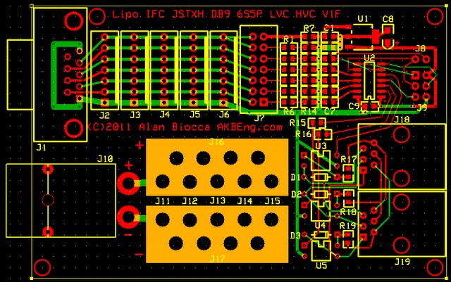
1) Battery Interface (one per bank), including:
a) cell balancing parallel connectors (done)
b) balancing charger connector (6S DB9) (done)
c) charge current connector (PowerPole15) (done)
d) cell monitoring microprocessor (features below are in design version, not yet built)
e) high current paralleling
f) LVC output (to communications bus)
g) HVC output (to communications bus)
h) communications bus
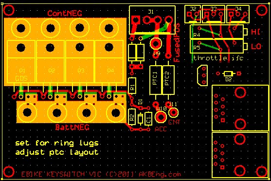
2) Keyswitch Interface, including:
a) keyswitch controlled FETs for precharge and operate, with off/remove, accessory, and operate modes
b) throttle spanning pots for Magura throttle
c) throttle clamping for LVC
d) HVC output (breakout from communications bus)
e) motor temperature electronics for K thermocouple
f) communications bus
3) Master Controller, including: (partially designed, partially commercial)
a) LCD display for readout of parameters such as cell voltages
b) pushbuttons
c) microprocessor with significant memory
d) buzzer
e) communications bus
4) Charge Controller, including: (this is not designed, so could be several versions from simple switch to micro controlled BOOST switcher...)
a) FET or relay switch to control external bulk charger/power supply from simple HVC line of communications bus (base design)
b) micro to monitor cell voltages from communications bus and control charging more intelligently (option)
c) charge voltage and current sensing
d) charge current control with switchmode FET and inductor, BUCK or possibly BOOST??? (options)
e) communications bus
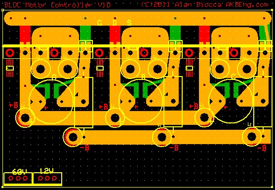
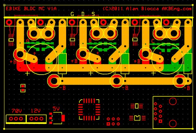
5) Motor Controller, including: (partially designed)
a) six TO247 FETs (100V parts, 85V 20S LiPo / 32S LiFePO4 design) (approx 50A battery current, 100A phase current)
b) proper FET gate drive
c) BLDC controller (built into micro)
d) microprocessor
e) pre-regulator and 12V switcher
f) 5v regulator
g) voltage and current sense
h) Cycle Analyst connector
i) throttle, ebrake, the usual I/O such as phase wires and battery wires
j) communications bus
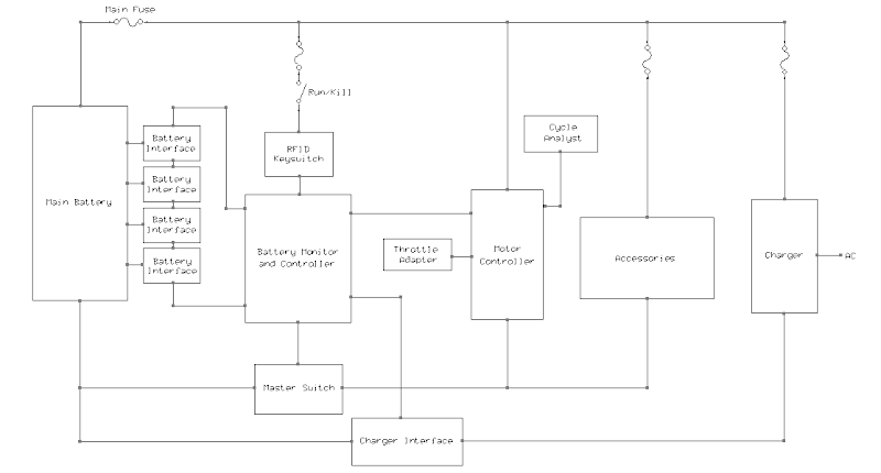
The communications bus is designed to be simple yet adequate (and similar to existing systems). It contains:
a) optically isolated LVC bus (really throttle cut, can be used for other purposes like motor or controller overheat)
b) optically isolated HVC bus (for controlling bulk chargers)
c) optically isolated serial in and out bus, master-slave type
d) 8 pin RJ-45 connectors. Two on most boards, so they can be easily daisy chained. The motor controller only has one RJ-45 due to space constraints.
In a simple system the LVC and HVC can be used without using the serial bus. These are similar to other existing designs and so should be compatible with them and their modules. The serial bus is only used if there is a higher level controller present that needs to use it and gain access to more information such as cell voltages and motor and controller temperatures. Just snap together short RJ cables between the modules to carry the busses to all the cards.
All boards are presently in some state of partial design, some more advanced than others. The new version of the Battery Interface is quite far along, probably 90%. The motor controller is partially laid out, about 40%. The keyswitch board is pretty far along, about 70%. But it is not too late to make changes. Much easier to rip up CAD than toss built electronics. Even built electronics are not too hard to toss if there are only a few made. This project is optimized for small incremental production.
These boards are all 2.5 by 3.8 inches to fit the expressPCB MiniBoard service, three boards cheap and quick. Makes it easy to try a different design. No huge commitment on pc boards.
I'm trying to keep the pieces simple but make their sum equal more than their parts. They can work with other designs, and they can combine into a greater system at different levels. For example the Master Controller is not needed. If present more features would be possible. A Cycle Analyst can be used with this system. Eventually the Master Controller might be able to do most of those functions, but initially the plan is to focus on doing things the CA does not do so the two displays are complementary. Having more display area can be better allowing the displays to be more fixed making it easier to find information by location on the display rather than pushing buttons to scroll it into view.
So a simple system could be just a couple of Battery interface boards to get to 12S LiPo (or LiFePO4), and a keyswitch board. This handles precharge, a Magura throttle if desired, motor temperature overheat shutdown, LVC to the throttle clamp, and the HVC signal is available. Basic and rugged, but protects against overdischarge and motor overheat. This is my "next step" in the progression.
Later I will add other modules such as the Master Controller, Charge Controller and Motor Controller. In the mean time other available modules are performing those roles (to some degree) so we don't have to wait for them to enjoy our eBike!
Interesting Components List:
100V TO264 FETs: IRFP4468
75V TO264 FETs: IRFP4368
100V TO220 FETs
FET drivers: IRS2186S SOIC8
Capacitors: 220uF 100V Rubycon, combined with smaller caps for low impedance over a wide freq range
motor control micro: ATMega32M1 in TQFP32 with BLDC motor support hardware on-chip, 32K code, etc
small micro: ATtiny84
12v TO220 switching reg
5v ultra low drain reg
optical isolators
K thermocouple interface
Terminal micro subsystem: Olimex ATmega128 (Sparkfun)
graphical LCD display
keyswitch
References:
Lipo Battery Interface http://endless-sphere.com/forums/viewtopic.php?f=14&t=27812
Commuter Controller: http://endless-sphere.com/forums/viewtopic.php?f=2&t=22630
Simple BLDC Controller: http://endless-sphere.com/forums/viewtopic.php?f=2&t=23350
Ricky's Hi Power Controller: http://endless-sphere.com/forums/viewtopic.php?f=2&t=23205
Quad Cell BMS Discussion http://endless-sphere.com/forums/viewtopic.php?f=14&t=21939
my eBike build testbed for this project: http://endless-sphere.com/forums/viewtopic.php?f=3&t=21390
Build something, and then make it better...
Thanks in advance for your comments,
(Note - this has evolved a bit, jump to near the end of this page for the 2013 version, or review the earlier version here)
I'm thinking about putting together the different things I'm building to make a somewhat unified "control system" on my eBike. I thought it might be interesting to discuss this and get input and comments.
I've partially designed a number of these items, and built a couple versions of the Battery interface, so things are starting to take shape. At this time the elements of my planned eBike control system are:
1) Battery Interface (one per bank), including:
a) cell balancing parallel connectors (done)
b) balancing charger connector (6S DB9) (done)
c) charge current connector (PowerPole15) (done)
d) cell monitoring microprocessor (features below are in design version, not yet built)
e) high current paralleling
f) LVC output (to communications bus)
g) HVC output (to communications bus)
h) communications bus
2) Keyswitch Interface, including:
a) keyswitch controlled FETs for precharge and operate, with off/remove, accessory, and operate modes
b) throttle spanning pots for Magura throttle
c) throttle clamping for LVC
d) HVC output (breakout from communications bus)
e) motor temperature electronics for K thermocouple
f) communications bus
3) Master Controller, including: (partially designed, partially commercial)
a) LCD display for readout of parameters such as cell voltages
b) pushbuttons
c) microprocessor with significant memory
d) buzzer
e) communications bus
4) Charge Controller, including: (this is not designed, so could be several versions from simple switch to micro controlled BOOST switcher...)
a) FET or relay switch to control external bulk charger/power supply from simple HVC line of communications bus (base design)
b) micro to monitor cell voltages from communications bus and control charging more intelligently (option)
c) charge voltage and current sensing
d) charge current control with switchmode FET and inductor, BUCK or possibly BOOST??? (options)
e) communications bus
5) Motor Controller, including: (partially designed)
a) six TO247 FETs (100V parts, 85V 20S LiPo / 32S LiFePO4 design) (approx 50A battery current, 100A phase current)
b) proper FET gate drive
c) BLDC controller (built into micro)
d) microprocessor
e) pre-regulator and 12V switcher
f) 5v regulator
g) voltage and current sense
h) Cycle Analyst connector
i) throttle, ebrake, the usual I/O such as phase wires and battery wires
j) communications bus
The communications bus is designed to be simple yet adequate (and similar to existing systems). It contains:
a) optically isolated LVC bus (really throttle cut, can be used for other purposes like motor or controller overheat)
b) optically isolated HVC bus (for controlling bulk chargers)
c) optically isolated serial in and out bus, master-slave type
d) 8 pin RJ-45 connectors. Two on most boards, so they can be easily daisy chained. The motor controller only has one RJ-45 due to space constraints.
In a simple system the LVC and HVC can be used without using the serial bus. These are similar to other existing designs and so should be compatible with them and their modules. The serial bus is only used if there is a higher level controller present that needs to use it and gain access to more information such as cell voltages and motor and controller temperatures. Just snap together short RJ cables between the modules to carry the busses to all the cards.
All boards are presently in some state of partial design, some more advanced than others. The new version of the Battery Interface is quite far along, probably 90%. The motor controller is partially laid out, about 40%. The keyswitch board is pretty far along, about 70%. But it is not too late to make changes. Much easier to rip up CAD than toss built electronics. Even built electronics are not too hard to toss if there are only a few made. This project is optimized for small incremental production.
These boards are all 2.5 by 3.8 inches to fit the expressPCB MiniBoard service, three boards cheap and quick. Makes it easy to try a different design. No huge commitment on pc boards.
I'm trying to keep the pieces simple but make their sum equal more than their parts. They can work with other designs, and they can combine into a greater system at different levels. For example the Master Controller is not needed. If present more features would be possible. A Cycle Analyst can be used with this system. Eventually the Master Controller might be able to do most of those functions, but initially the plan is to focus on doing things the CA does not do so the two displays are complementary. Having more display area can be better allowing the displays to be more fixed making it easier to find information by location on the display rather than pushing buttons to scroll it into view.
So a simple system could be just a couple of Battery interface boards to get to 12S LiPo (or LiFePO4), and a keyswitch board. This handles precharge, a Magura throttle if desired, motor temperature overheat shutdown, LVC to the throttle clamp, and the HVC signal is available. Basic and rugged, but protects against overdischarge and motor overheat. This is my "next step" in the progression.
Later I will add other modules such as the Master Controller, Charge Controller and Motor Controller. In the mean time other available modules are performing those roles (to some degree) so we don't have to wait for them to enjoy our eBike!
Interesting Components List:
100V TO264 FETs: IRFP4468
75V TO264 FETs: IRFP4368
100V TO220 FETs
FET drivers: IRS2186S SOIC8
Capacitors: 220uF 100V Rubycon, combined with smaller caps for low impedance over a wide freq range
motor control micro: ATMega32M1 in TQFP32 with BLDC motor support hardware on-chip, 32K code, etc
small micro: ATtiny84
12v TO220 switching reg
5v ultra low drain reg
optical isolators
K thermocouple interface
Terminal micro subsystem: Olimex ATmega128 (Sparkfun)
graphical LCD display
keyswitch
References:
Lipo Battery Interface http://endless-sphere.com/forums/viewtopic.php?f=14&t=27812
Commuter Controller: http://endless-sphere.com/forums/viewtopic.php?f=2&t=22630
Simple BLDC Controller: http://endless-sphere.com/forums/viewtopic.php?f=2&t=23350
Ricky's Hi Power Controller: http://endless-sphere.com/forums/viewtopic.php?f=2&t=23205
Quad Cell BMS Discussion http://endless-sphere.com/forums/viewtopic.php?f=14&t=21939
my eBike build testbed for this project: http://endless-sphere.com/forums/viewtopic.php?f=3&t=21390
Build something, and then make it better...
Thanks in advance for your comments,
")