Dual rotor axial flux motor design

Miles said:
Accepting some imbalance, I'm leaning towards increasing the number of turns from 4 to 6 and missing out the first half turn from the first module of each phase. Might as well gain the advantage of losing an endturn, too :D

Reasonable compromise?
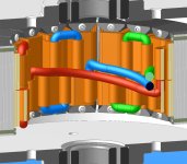
I kept the endturn for the sake of uniformity :)

It makes for a neat connection.
 

Attachments

  • External-connections.jpg
    External-connections.jpg
    50.9 KB · Views: 4,488
Data for the 6t wind:

Kv 100 rpm/V (estimated)
Kt 0.0955 Nm/A (estimated)
Rm 8.8 milliohms (calculated)
Nominal speed 4000 rpm
Flux frequency at nominal speed 533 Hz
Core volume 8.5222E4 cubic mm (calculated)
Core mass 0.672 kg (calculated)
Voltage @ nominal speed 40V
Total parasitic losses @ nominal speed (Arnolds thin gauge GO 0.15mm @ 1.5T) 40 Watts (estimated)
No load amps @ 40V 1amp (estimated)
 
Comparison with Astro 3220 7t which weighs the same as my 'motor' and has the same torque constant. Not fair to compare theoretical against empirical but interesting nevertheless...
 

Attachments

  • Comparison-1.jpg
    Comparison-1.jpg
    53.4 KB · Views: 4,384
8X less loss at the current limit would be nice. If you can come anywhere close to predicted it will be great.
 
Bling! :mrgreen:
 
fechter said:
Solid gold windings should have less resistance than copper. :wink:
You'd think so but apparently not, which is why they are gold plated silver :wink:

Ref: http://www.thecarpcstore.com/cms/index.php?option=com_content&view=article&id=51&Itemid=68
 
Miles said:
fechter said:
Solid gold windings should have less resistance than copper. :wink:
You'd think so but apparently not, which is why they are gold plated silver :wink:

Ref: http://www.thecarpcstore.com/cms/index.php?option=com_content&view=article&id=51&Itemid=68
Sounds like a cheep build so lets get to production.
 
Plating: I believe that to assuage intermetalics between layers that it needs to be Copper-Nickel-Gold. 8)

Quick, place it under glass so it won't get dirty...
A jewel to behold in any Keep! KF
 
Miles said:
fechter said:
Solid gold windings should have less resistance than copper. :wink:
You'd think so but apparently not, which is why they are gold plated silver :wink:
I stand corrected :oops:
We'll just have to wait until we can get graphene sheets.
 
fechter said:
Miles said:
fechter said:
Solid gold windings should have less resistance than copper. :wink:
You'd think so but apparently not, which is why they are gold plated silver :wink:
I stand corrected :oops:
We'll just have to wait until we can get graphene sheets.
I have a feeling it will be sprayed on or polished on. I have graphite sheets for conducting heat and power out of my fets... All you need to do is coat something with a smothe thin layer of it then coat it with somehting to stop it from rubbing off.
 
I followed this thread to this point but it seems that you have abandoned this design in favor of a radial design. Could you give a brief summery of why you decided to switch designs..
 
I've started re-working this design. Diameter increased to 126mm and it's now configured for 24t 22p. I'll turn the coils inside out so, the crossover and inter-connections will now be on the outside.....
 

Attachments

  • 24t-22p-configuration.png
    24t-22p-configuration.png
    155 KB · Views: 3,226
How do we hold those parts to form a 1 piece stator and how do we cool that?
 
Back
Top