Nickel Strip ratings

Ham

10 kW
Joined
Feb 18, 2016
Messages
501
Hi All,

I am just wondering if someone can point me to a chart or resource that will show me the current ratings for this:

https://eu.nkon.nl/accessories/battery-solder-strip/nikkel-batterijpack-verbinding-soldeerstrip-27mm.html

nickel strip 27mm x 0.15m.

I have asked Nkon and they don't know!

Thanks
 
spinningmagnets said:
If it is truly 0.15mm pure nickel, it should be fine for 10A per cell.

Thank you, 10a per cell, continuous or peak? ...any tips on how I work that out on a pack basis? I have 196 cells in my pack...I assume I use the parallel count as it is the paralleling of cells that ups our amp hours?!
 
196 cells is a lot. You haven't mentioned the voltage or how many cells are in parallel.

When using the ladder-shaped nickel bus material, the series and parallel current paths are both the same width and thickness. This adds physical reinforcement to the pack, since nickel is very stiff. That being said, the parallel paths can be much thinner and narrower, because the current they carry is very low under all conditions. The issue of concern is all of the series current paths.

If you are using 14S then the P-count is 14P. At 10A per cell, that's 140A. That ladder-bus strip can handle that, but the two ends of the pack cannot. You will need to overlay the positive and negative ends with thick copper as a collector.

BatteryBusBars2.png
 
Thanks guys.

We built the pack as two 6s16p so I can join them together in series to make a 12s16p pack on the bike and have a modular pack for future builds I have planned.

We ran the main pos and neg leads the full length of packs with 8awg and xt150 anti spark terminals. You are recommending we add a strip along the end of the pack also?
 
16P would be 160A at 10A per cell. You asked if that was continuous or peak. The answer relies on the duty cycle. If you acceleration phase is very short, you can go to a higher temporary peak, since the longer cruise phase allows the rest of the bus mass to absorb any of the heat that is generated, and to then shed it over time.

If this is for a racing battery, it only needs to survive one race, which means you can lean the duty cycle calculations towards the warm end. 160A is motorcycle territory, so...you posted in the E-bike technical section. There is nothing wrong with having a large battery on an ebike that can put out high amps. Doing that can mean that when running under a mild duty-cycle, the battery doesn't get hot, and it will last a very long time.

If this is a project where you are keeping the details confidential, no sweat, you can contact me in a PM. You can add a dozen temp probes on the pack, and then run it in the designed user-profile, then the data can reveal any hot spots.

If you find a hot-spot (high resistance, or normal resistance with too many amps at a bottleneck), then you can bridge that hot spot by overlaying it with copper wire. Warm is good (you can hold your hand/finger on that spot continuously), but hot is bad. Even if you are not concerned about the longevity of the pack, a performance pack should avoid voltage drop across bottlenecks.

What controller do you plan to use? and also, do you have pics of the pack and the 8ga wire on the pos/neg collectors, that you would be willing to share?
 
Thanks Spinning Magnets, nothing is confidential by any means.

The pack is on an ebike yes and was built for pack performance and longevity as the small amp draw (relative to what it could theoretically pump out) is low.

I am currently running a Castle talon 120 and will be moving back to the HV160 at some point.

My initial question has come from hunting voltage sag in the system. I built the pack to try and eliminate sag and have only succeeded a small amount from hobby king lipo bricks, although overall performance is improved I still see more sag than I would have expected from this pack.

I have replaced all bike wiring for 8awg, connectors from xt90 to 150 and also have a bigger shunt now too. Sag looks to be caused by the pack itself now although the esc still has three internal xt90 connectors, I am yet to try the castle hv160 which is now with xt150 connectors throughout.

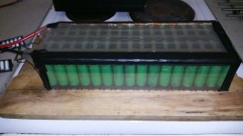
IMG-20181205-WA0002.jpeg

The image is of one of the 6s16p packs and does not offer the best view I understand, but hopefully you can see the copper 8awg wiring along the top running the length of the pack.

Thanks Matador for the table although I am a little confused as the nickel strip I used says 27x0.15 and your chart goes to 10mm? Would I be right in thinking then that I should measure the width of the narrowest section of mine?
 
Right,
27 mm strips is less typical of a width. Most use width of up to 10 mm. Your is almost 3 times wider (which is good).

But what matters is the conducting cross sectionnal surface area (in mm2)... In your case, 27 mm width x 0.15 mm thickness is 4.05 mm^2 CSA. In terms of gauge, 4.05 mm^2 is equivalent to about 12 AWG, that is, IF your strips were made out of copper.

But for nickel 4.05 mm^2 CSA (or 27 mm width x 0.15mm thick) is good for about 15 AMPS, with a resistivity of around 17.5 mΩ/meter of strip...

If these same strips 4.05 mm^2 CSA (or 27 mm width x 0.15mm thick) were made of copper instead of Nickel, they would be good for about 43 AMPS, with a resistivity of around 4.20 mΩ/meter of strip.

Matador
 
Thank you!

If I were to run a bead of solder across the series connections would that help or is that a silly idea?
 
They are not really 27mm though. That's the total width of the strip, but the interconnects between cells are more like 10mm. Measure the width of the interconnects and then refer to the chart above. I would say they are good for about 6A if they are 10mm.

nickel-batterypack-connection-strip-2.jpg


I don't think coating the interconnects with solder will help much. Solder doesn't have the best current carrying capability. You would be better of doubling up the use of the nickel strips, or finding some thicker nickel strips.

To get 10A/cell you really want 10mm x 0.3mm strips.
 
Thanks Lionman,

I will see if i can borrow the spot welder again at some point and add more of these strips.

Would it be necessary to add them to all connections or just across the series cross overs?
 
Ham said:
Thanks Lionman,

I will see if i can borrow the spot welder again at some point and add more of these strips.

Would it be necessary to add them to all connections or just across the series cross overs?

Just the series connections. The parallel connections shouldn't see any more than an amp or so in a well constructed pack... They should only be subjected to more if there was a bad cell or cell connection.

What is the width of the series connections on those strips do you know?
 
Well I just pulled the spare roll I have and it is no more than 7mm at any one point...seems I have found my sag issues!?
 
spinningmagnets said:
196 cells is a lot. You haven't mentioned the voltage or how many cells are in parallel.

When using the ladder-shaped nickel bus material, the series and parallel current paths are both the same width and thickness. This adds physical reinforcement to the pack, since nickel is very stiff. That being said, the parallel paths can be much thinner and narrower, because the current they carry is very low under all conditions. The issue of concern is all of the series current paths.

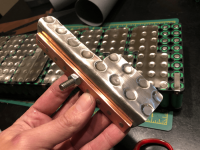
If you are using 14S then the P-count is 14P. At 10A per cell, that's 140A. That ladder-bus strip can handle that, but the two ends of the pack cannot. You will need to overlay the positive and negative ends with thick copper as a collector.
file.php

Hello,

This busbar design is beautiful. Would you be able to share the process and materials used to create those plates? I'm particularly interested in how the copper bar was attached to the (nickel?) plate. I have experience with resistance welding copper and it was a nightmare.

Thanks in advance.
 
Back
Top