
You are using an out of date browser. It may not display this or other websites correctly.
You should upgrade or use an alternative browser.
You should upgrade or use an alternative browser.
Analog electronic soft start E-bike throttle solution.
- Thread starter TommyCat
- Start date
TommyCat
10 kW
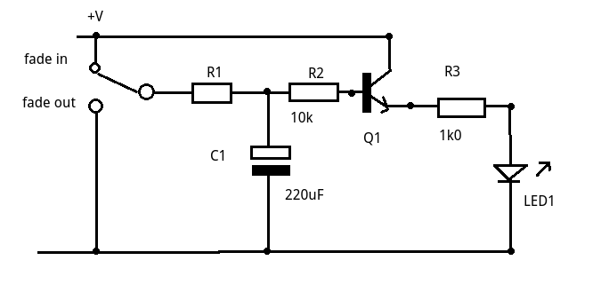

I sort of remember building that on a breadboard but don't recall the values used. The resistors in series with the diodes will determine the ramp up and ramp down rates. I can't think of a reason why you'd want a slow ramp down. For safety, when you let off the throttle, the output should drop immediately. The values of the resistors and the capacitor will set the timing. You could pick some random values and try them in Spice to see what happens when you give a sudden input change.
These days, you could do this with an Arduino and make it programmable.
These days, you could do this with an Arduino and make it programmable.
I dug around in my files and found a more recent version of the circuit. The 1M pot adjusts the ramp up rate. Ramp down is as fast as possible. There are many different op-amps that could work. TLC2262 is something that I happened to have lying around.

TommyCat
10 kW
Excellent,
Thank you for your quick response.
")
Did a bit of programming in a different field a while back. Great satisfaction when it’s done and working well, but huge learning curve and frustration. Something I’d rather pass on, and learn something new. But others may enjoy the challenge on this path.
So did you bench test this?
Drawing it up on Spice, thanks again!
Thank you for your quick response.
I can't think of a reason why you'd want a slow ramp down. For safety, when you let off the throttle, the output should drop immediately.
These days, you could do this with an Arduino and make it programmable
Did a bit of programming in a different field a while back. Great satisfaction when it’s done and working well, but huge learning curve and frustration. Something I’d rather pass on, and learn something new. But others may enjoy the challenge on this path.
So did you bench test this?
Drawing it up on Spice, thanks again!
TommyCat
10 kW
Your op amp wasn't available, and just put in a 70K resistor for the pot where it became stable... this is the resulting plot.
The input variable voltage is a custom voltage mapping that mimics possible throttle voltage outputs. (Sharply changes... but gives insight to how the circuit reacts...)

I got my LTspice simulator here if anyone wants to lose track of time...
https://www.analog.com/en/resources/design-tools-and-calculators/ltspice-simulator.html
The input variable voltage is a custom voltage mapping that mimics possible throttle voltage outputs. (Sharply changes... but gives insight to how the circuit reacts...)
I got my LTspice simulator here if anyone wants to lose track of time...
https://www.analog.com/en/resources/design-tools-and-calculators/ltspice-simulator.html
Nice. It's a bit hard to see the blue output line, but it looks like it is intended. You can change the value of R5 to see what the ramp time is.
TommyCat
10 kW
Thanks for the input. Tried to make the plots look easier to see.Nice. It's a bit hard to see the blue output line, but it looks like it is intended.
My goal was to be able to change the delay time between 0 and 2 seconds, just to see.You can change the value of R5 to see what the ramp time is.
But I discovered instability when the R5 resistance is less than 70K or greater than 120K. 150K gave a 1/2 second delay for reference...
I don't know it this oscillation should be of a concern and eliminated or ignored...?


I used a comparable op-amp. Circuit draw up O.K.?
Oh interesting... Wild guess the diode capacitance is making it misbehave.
Circuit draw looks good.
Maybe try placing a 1k resistor in series with D2 and see if it goes away.
In real life, if that oscillation occurs, it may not be noticeable since the throttle input to the controller will generally have some kind of RC filter, but oscillations are undesirable and good to avoid.
Last edited:
TommyCat
10 kW
Good call. 1K was just a tad strong with a bit of unwanted voltage drop hang near the bottom. But a 800-ohm resistor makes it work perfectly! Well done.Maybe try placing a 1k resistor in series with D2 and see if it goes away.
In real life, if that oscillation occurs, it may not be noticeable since the throttle input to the controller will generally have some kind of RC filter, but oscillations are undesirable and good to avoid.
TommyCat
10 kW


If you want it slower, increase the value of C1.
TommyCat
10 kW
I think you could get there with more resistance on R5. And you have a great linear output.
But to be particular, I'm shooting for a profile plot that looks more like this... very gradual at start and increasing to catch up.

But to be particular, I'm shooting for a profile plot that looks more like this... very gradual at start and increasing to catch up.
You'd probably want that profile to be made downstream of the rate limiter. There are several ways to do it but all of them are pretty complicated. An Arduino is one way, and that may be the easiest. I'll see if I can think of a relatively simple analog way.
zachleedogg
1 mW
- Joined
- Apr 4, 2021
- Messages
- 11
I once had the opportunity to meet the creator of LTspice. I told him the blue line color should be the LAST default color for any trace. He told me just to change the color manually ¯\_(ツ)_/¯Nice. It's a bit hard to see the blue output line, but it looks like it is intended. You can change the value of R5 to see what the ramp time is.
TommyCat
10 kW
Looking forward to your solution!I'll see if I can think of a relatively simple analog way.
Are you using a circuit simulator?
If I can help in any way, let me know.
I appreciate the fact that you CAN change the graphics.He told me just to change the color manually
My problem is I keep running into not finding the components in the library to insert in the circuit.
But a very impressive free software tool IMHO.
I looked at several possible designs, but none of them really look good to me. There were a few that used a diode as a non-linear amplifier, but in this application, there would likely be unacceptable temperature drift. The Arduino is really the way to go if you want to change the shape of the curve.
That said, if the goal is to make the low end of the throttle less sensitive for better low speed control, making a current mode throttle works well. Maybe not a true current mode, but more power mode, where the battery current is limited by the throttle setting. I built something like this ages ago and it worked.
A Cycle Analyst can do some of these tricks too.
TommyCat
10 kW
This is right on the money!if the goal is to make the low end of the throttle less sensitive for better low speed control
Don't quite follow you here... could you expand on this?making a current mode throttle works well. Maybe not a true current mode, but more power mode, where the battery current is limited by the throttle setting.
For that, your system would need to monitor battery current, and throttle input, and wheel speed.
At low wheel speed, if battery current increases (too quickly) or speed increases (too quickly) throttle output is reduced until that behavior stops, and either slowly increases BC or S, or maintains the same BC or S.
Depends on the specific behavior you want.
It is part of the various throttle modes of the CA, except that the CA doesn't affect just part of the curve for W, A, or S, it affects the whole thing as it doesn't have a way to set a curve shape. Sometimes you can tweak the ramping or PID parameters for the various loops to give other than linear behavior, but it isn't exactly like what you're trying to do (assuming you want no limiting outside the low-end-speed range).
FWIW, any FOC controller (other than some Kellys, AFAICR) modulates motor torque, not motor speed, via the throttle input, and would usually be easier to control at low speed even with a plain linear throttle, even with a system that has a lot more power than needed for the situation.
I dont' think he ever published the code or circuit, but ZombieSS's Throttle Tamer was designed to do what you're trying to do, AFAICT. I tried to find the threads for it, but neither one of them exists anymore for some reason, even in the old forum archive (a shame as I recall there was good useful info there; I wonder how many other such missing threads there are?)
EDIT: found a version of the sale thread on archive.org
but there's not much there, it didn't grab any of the files (manual, etc).
Another version has images but no manual
manual found here via google
but I can't make a link that works, so I just attached the file instead.

A version of the development thread on archive.org
but the archive ends before he got it finished. :/
"HomeIO" posted that they had created something that could do it, but never posted anything useful to us, just some screenshots and descriptions of things it supposedly could do, but nothing about what they actually used to do it, or techniques, etc., so the thread is pretty useless. Link below in case you're curious anyway:

 endless-sphere.com
GWhy has a thread that might be helpful if you use an MCU type system to do it (haven't read it in years, so can't recall what specifically is in there)
endless-sphere.com
At low wheel speed, if battery current increases (too quickly) or speed increases (too quickly) throttle output is reduced until that behavior stops, and either slowly increases BC or S, or maintains the same BC or S.
Depends on the specific behavior you want.
It is part of the various throttle modes of the CA, except that the CA doesn't affect just part of the curve for W, A, or S, it affects the whole thing as it doesn't have a way to set a curve shape. Sometimes you can tweak the ramping or PID parameters for the various loops to give other than linear behavior, but it isn't exactly like what you're trying to do (assuming you want no limiting outside the low-end-speed range).
FWIW, any FOC controller (other than some Kellys, AFAICR) modulates motor torque, not motor speed, via the throttle input, and would usually be easier to control at low speed even with a plain linear throttle, even with a system that has a lot more power than needed for the situation.
I dont' think he ever published the code or circuit, but ZombieSS's Throttle Tamer was designed to do what you're trying to do, AFAICT. I tried to find the threads for it, but neither one of them exists anymore for some reason, even in the old forum archive (a shame as I recall there was good useful info there; I wonder how many other such missing threads there are?)
EDIT: found a version of the sale thread on archive.org
but there's not much there, it didn't grab any of the files (manual, etc).
Another version has images but no manual
manual found here via google
but I can't make a link that works, so I just attached the file instead.
A version of the development thread on archive.org
but the archive ends before he got it finished. :/
"HomeIO" posted that they had created something that could do it, but never posted anything useful to us, just some screenshots and descriptions of things it supposedly could do, but nothing about what they actually used to do it, or techniques, etc., so the thread is pretty useless. Link below in case you're curious anyway:
Throttle Master (Throttle Remapping and Filtering tool)
I have made a device called Throttle Master. Here is a small set of its features. It can convert a hall throttle to pot output. It can convert pot throttle to hall output. It can remap the output to eliminate dead zones. It can smooth the throttle to completely remove any jerkyness. It...
GWhy has a thread that might be helpful if you use an MCU type system to do it (haven't read it in years, so can't recall what specifically is in there)
Throttle Current/phase power control
Arduino code for throttle interface that allows current and phase limiting to be pre set. Original code was by Hornet Dave for use with RC controllers : original thread is here http://endless-sphere.com/forums/viewtopic.php?f=30&t=33947 EDIT: A link to my watt/volt meter that can also use...
Attachments
TommyCat
10 kW
Hiyas amberwolf,
Thanks for your input, and the links.
Not really interested on a current modifying solution, just want to control the voltage output of the throttle as desired.
In a strictly analog way, no programming or the like.
In my novice way I was also thinking of a resistive component, that would start with a set resistance (let the cap start to fill) then gradually release. Like an NTC thermistor or something similar in operation?
Thanks for your input, and the links.
Not really interested on a current modifying solution, just want to control the voltage output of the throttle as desired.
In a strictly analog way, no programming or the like.
I looked at several possible designs, but none of them really look good to me. There were a few that used a diode as a non-linear amplifier
In my novice way I was also thinking of a resistive component, that would start with a set resistance (let the cap start to fill) then gradually release. Like an NTC thermistor or something similar in operation?
Sorry I've been away for a while.
I've had several scooters where the low speed throttle response was an issue. It's really nice when it's dialed in properly.
If the motor controller was fancy and fully programmable, this could be fixed by proper programming, but my scooters had cheap controllers with limited or no programming options.
There are a couple of factors that make this an issue.
First, look at the response of the throttle output voltage vs. throttle positon.

If you look at the curve, you'll see that it is not a straight line linear response. It's sort of "S" shaped with curved portions at the ends. The other thing to notice is the motor start voltage is quite a bit higher than the lowest throttle output. The motor start voltage has to be higher than the lowest throttle output to make sure the motor turns off when you release the throttle. Due to large variations in construction and things like temperature drift, manufacturers make a large tolerance here.
But this makes the starup happen on the steep part of the graph. If you could lower the motor start voltage, you could get it on the curved part near the end where the slope is much flatter. Since cheap controllers don't have programmable motor start voltages, the way around this is to place a resistor in series with the ground wire going to the throttle. This will shift the whole curve upward at the bottom end as shown by the green line below.

By using a multi-turn trimmer pot, you can adjust the pot so the motor barely starts running, then back off a bit. This makes a HUGE difference in the controllability at low speeds. On mine, the right resistance was around 150 ohms.
The other big factor is the controller's "operating mode", by this I mean whether it's a speed command, torque command, or something in between. Typical cheap controllers are really neither, but "PWM" command, where the throttle input controls the PWM duty cycle independent of any feedback.
With PWM command or speed command, a small, sudden increase in throttle makes the controller put out FULL power (limited only by the controller's current limit or BEMF) for a short time as the new operating point is reached.
If the controller uses a current (torque) command, a small sudden increase in throttle results in a small sudden increase in current, which is barely noticeable.
Years ago, I built a circuit that measures the battery current by using a section of the existing controller battery wire as a shunt and an op-amp that adjusts the throttle voltage to keep the battery current at level determined by the throttle setting.

This circuit took a while to get dialed in, but once adjusted, worked great. This totally eliminates the tendency to get large power surges at low speeds. The bypass switch allows you to go back to normal PWM mode and doesn't require any mods to the controller itself.
On one of my scooters, the trigger throttle was integrated into a display unit and the hall sensor was a tiny thing on a board with no easy way to mess with the wiring. On this scooter, I was able to take a small chunk of magnet and placed it in the right spot with double sticky tape to lift the low end of the curve so it behaved like the green line in the graph above. This worked great but was tricky to find the right spot for the magnet. The stock throttle magnet is to the left of the sensor in the picture:

I've had several scooters where the low speed throttle response was an issue. It's really nice when it's dialed in properly.
If the motor controller was fancy and fully programmable, this could be fixed by proper programming, but my scooters had cheap controllers with limited or no programming options.
There are a couple of factors that make this an issue.
First, look at the response of the throttle output voltage vs. throttle positon.
If you look at the curve, you'll see that it is not a straight line linear response. It's sort of "S" shaped with curved portions at the ends. The other thing to notice is the motor start voltage is quite a bit higher than the lowest throttle output. The motor start voltage has to be higher than the lowest throttle output to make sure the motor turns off when you release the throttle. Due to large variations in construction and things like temperature drift, manufacturers make a large tolerance here.
But this makes the starup happen on the steep part of the graph. If you could lower the motor start voltage, you could get it on the curved part near the end where the slope is much flatter. Since cheap controllers don't have programmable motor start voltages, the way around this is to place a resistor in series with the ground wire going to the throttle. This will shift the whole curve upward at the bottom end as shown by the green line below.
By using a multi-turn trimmer pot, you can adjust the pot so the motor barely starts running, then back off a bit. This makes a HUGE difference in the controllability at low speeds. On mine, the right resistance was around 150 ohms.
The other big factor is the controller's "operating mode", by this I mean whether it's a speed command, torque command, or something in between. Typical cheap controllers are really neither, but "PWM" command, where the throttle input controls the PWM duty cycle independent of any feedback.
With PWM command or speed command, a small, sudden increase in throttle makes the controller put out FULL power (limited only by the controller's current limit or BEMF) for a short time as the new operating point is reached.
If the controller uses a current (torque) command, a small sudden increase in throttle results in a small sudden increase in current, which is barely noticeable.
Years ago, I built a circuit that measures the battery current by using a section of the existing controller battery wire as a shunt and an op-amp that adjusts the throttle voltage to keep the battery current at level determined by the throttle setting.
This circuit took a while to get dialed in, but once adjusted, worked great. This totally eliminates the tendency to get large power surges at low speeds. The bypass switch allows you to go back to normal PWM mode and doesn't require any mods to the controller itself.
On one of my scooters, the trigger throttle was integrated into a display unit and the hall sensor was a tiny thing on a board with no easy way to mess with the wiring. On this scooter, I was able to take a small chunk of magnet and placed it in the right spot with double sticky tape to lift the low end of the curve so it behaved like the green line in the graph above. This worked great but was tricky to find the right spot for the magnet. The stock throttle magnet is to the left of the sensor in the picture:
Last edited:
TommyCat
10 kW
Hey, great to have you back.
I think we can agree that a voltage profile on a troublesome throttle would be a very helpful place to start before making changes.
You bring out several good points.
Do you think that a throttle soft start or delay feature would still be advantageous for high powered machines?
I like this bit of genius.
But a little fuzzy on the real-world workings...
Say you're going down the road, holding your speed at 10mph. You start going up an incline. With this circuit seeing the increased voltage current, would it then purposely slow you down more? Or does it only work at the low end?
Please expand in detail how this circuit works to help me understand...
And why all the different op-amp choices in your schematic?
I also like your mechanical solution for hall sensor voltage output manipulation. May I present it in my thread?
LOL, had to edit. Someone has the nic 10mph.
I think we can agree that a voltage profile on a troublesome throttle would be a very helpful place to start before making changes.
You bring out several good points.
Do you think that a throttle soft start or delay feature would still be advantageous for high powered machines?
I built a circuit that measures the battery current by using a section of the existing controller battery wire as a shunt and an op-amp that adjusts the throttle voltage to keep the battery current at level determined by the throttle setting.
I like this bit of genius.
But a little fuzzy on the real-world workings...
Say you're going down the road, holding your speed at 10mph. You start going up an incline. With this circuit seeing the increased voltage current, would it then purposely slow you down more? Or does it only work at the low end?
Please expand in detail how this circuit works to help me understand...
And why all the different op-amp choices in your schematic?
I also like your mechanical solution for hall sensor voltage output manipulation. May I present it in my thread?
LOL, had to edit. Someone has the nic 10mph.
With the current mode throttle, the throttle setting determines the current limit. The motor will try to go as fast as it can for the given limit. If you're traveling at a steady speed and hit a hill, it will slow down and you'll need to give more throttle to maintain speed. Basically, the throttle setting will control the torque output instead of the speed. If you're coasting along and just give a small amount of throttle, you'll get a small amount of torque regardless of speed. For very high powered motors, this works great at low speeds and the response is more like a gas engine.
From a dead stop, if you give part throttle, the acceleration will be steady until the motor reaches it's BEMF limit or until the supplied torque matches your wind+rolling resistance. If you want maximum acceleration, you have to give full throttle.
Any of the op-amps listed should work. I'm sure there are more that would also work. You just need one with rail-to-rail output. The ones listed are in DIP-8 packages, which I like for hand building on a perf-board.
Yes you can use the magnet hack in your thread. This would likely work with most throttles but tricky to find the right spot.
TommyCat
10 kW
Thank you for the detailed explanation,
My take away is that current controlled mimics a gas powered bike.
For fun will try to “simulate” your circuit.
Look for your addition to the thread soon.
My take away is that current controlled mimics a gas powered bike.
For fun will try to “simulate” your circuit.
Look for your addition to the thread soon.
You can simulate the op-amp part, but you need the controller's response to do a full simulation. Not likely to be in the component library. Since this uses a feedback loop, there is always the potential for oscillation, but I never had that problem on my setup.
When I had this on my old scooter, I frequently bypassed it back to normal mode because the hard takeoff was more fun. You could still do a full power takeoff with it on, but you had to give it full throttle quickly.
In operation, the throttle setting determines the current limit and the motor goes as fast as it can until it reaches that limit. At low throttle it was very controllable and eliminates the sudden burst of power you get with a small throttle increase. This probably improves your range.
Similar threads
- Replies
- 10
- Views
- 517
- Replies
- 4
- Views
- 973
- Replies
- 4
- Views
- 503