Analog electronic soft start E-bike throttle solution.

You’ve talked me out of the simulation for now.
I think I’ll stick with the delay/soft start idea at this time for the issue of excessive start power at the beginning of throttle twist.

Do you have a cruise circuit that will try to maintain SPEED at a certain throttle voltage output? Like an automobile… :unsure:
 
I don't have a specific circuit (Fechter might) but that just requires a speedometer with negative feedback to vary the throttle voltage down if the speed increases.

If the speedo is pulses, you can use an integrating opamp circuit and some caps to smooth it into a constant voltage.

You would need something (pot, etc) to create the setpoint for the speed each time you engage it, or for simpler usage (but more complex design) a button that captures the present speed and then does a form of sample-and-hold of that voltage to use to compare with the realtime speedo input.

There are various S&H chips that are more or less simple enough to use in an analog-only circuit.
Random examples
 

Attachments

  • lf198jan[1].pdf
    1.1 MB · Views: 1
  • AD582[1].pdf
    208.2 KB · Views: 1
Yes, I have a sample and hold circuit and a D flip flop for its actuation/release by pressing a momentary push button switch.

It's the first part... speed pulse integration with the components you mention that I could use help with.

.
 
There's a number of pages that explain opamp integration better than I could (it's been a long time since I worked with them), like this
https://www.electronics-tutorials.ws/opamp/opamp_6.html
or this
https://www.digikey.com/en/articles/analog-integrators-how-to-apply-them-for-sensor-interfaces
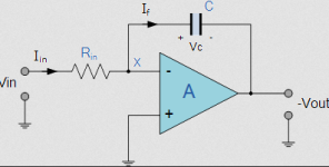
but basically the speed pulses go into the Vin, and the smoothed output (which may look like a sawtooth at this stage, depending on the RC combination chosen) at Vout, as an opposite of the input (meaning, voltage on the output should go *down* for the input rising), which if you need to you can fix with a second inverting opamp stage, which can also be used to scale the voltage for the next part of the circuit if needed.
1710797074829.png
 
The integrator circuit is what my throttle ramp circuit is based on. The diodes allow for a faster ramp down compared to the ramp up.
 
Will definitely be looking at this op amp circuit closer, thank you both for your inputs.

Recommendations for the signal input. I.E. speed sensor on the wheel with 1 rpm pulse. Or perhaps put a couple or more magnets for more signals? Or tap into a hall signal output?
 
More pulses per second will be easier to smooth out. More magnets on a wheel sensor gets you that easily enough, and they don't have to be perfectly evenly spaced (the result is smoother at slower speeds the more even they are, and the more of them there are).

Too many magnets too close together may blur the signal into just an "on" at too high a speed, and may also give too high a duty cycle so it doesn't vary the integrated voltage enough.

Without testing this, I *think* the easiest-to-smooth signal would be magnets on an "encoder ring" (like a PAS sensor) mounted at the hub of a wheel, where the magnets are all in the same polarity, if they don't end up too close together. Many geared hubmtoros use six magnets at around that same diameter circle aroudn the axle, just inside the cover, as a separate speed sensor from the halls.


A motor phase-hall signal will have a bunch of other noise on it that may affect the results; probably more noise the higher the phase currents are (more magnetic crap going on in the stator where the halls are mounted, and more possible induced currents into the hall wires).
 
If you wanted to make an analog "cruise control", one way would be to use a frequency to voltage converter like a LM2907 (see attached datasheet). You can use a hall sensor signal as the speed input and some other control (like the throttle) as the set point input. Using a hall signal will be better than a wheel sensor since it is much higher frequency, so will work at lower speeds. The LM2907 has a built in op-amp to perform the comparison of set point vs. speed input.

One issue will be when the speed is below the set point, the controller will get full throttle until it reaches the set point. You'd want to limit how fast it changes the throttle input.
 

Attachments

  • LM2907.pdf
    712.1 KB · Views: 1
If you wanted to make an analog "cruise control", one way would be to use a frequency to voltage converter like a LM2907 (see attached datasheet). You can use a hall sensor signal as the speed input and some other control (like the throttle) as the set point input. Using a hall signal will be better than a wheel sensor since it is much higher frequency, so will work at lower speeds. The LM2907 has a built in op-amp to perform the comparison of set point vs. speed input.

One issue will be when the speed is below the set point, the controller will get full throttle until it reaches the set point. You'd want to limit how fast it changes the throttle input.
This looks VERY interesting. Bit above my knowledge level but going to study it. Thank you.
 
... Bend it like Beckham. ;)

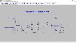
A usable circuit as modified?


Soft Start.jpg


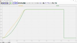
Soft Start Plot.jpg


Delay is easily adjusted by the R7 capacitor. Working on a potentiometer model to work in LTspice. :confused:
 
Adding C3 will slow things down and also make the response slightly non-linear. C1 and R4 were intended to control the speed and keep the response linear.

In practice, if the throttle ramp is linear, the current draw (and torque) will stay nearly steady during acceleration.

You could try it both ways and see what "feels" better.
 
You could try it both ways and see what "feels" better.

Right now I have an exponential ramp circuit. (Typical R/C type plotj
Your linear ramp circuit.
And a logarithmic ramp by modifying yours, that was my goal to achieve in my mind.

Granted, one might not be able to tell much if any difference between the three. But will see.

Is R1 just to dump the voltage charge from the op amp Input when the throttle is released?
 
R1 pulls the throttle signal down. It's there to make sure you have zero throttle if the throttle signal is disconnected.
 
Back
Top