14p20s ant bms need help

Pete's moto

10 mW
Joined
Dec 6, 2021
Messages
31
Location
Mtl
I've built a molicel 21700 p42a 20s14p for a dirtbike conversion(qs138 70h with em260 from electro co.)
Battery pack is done now and connected to Bluetooth reading 67v.
Not yet connected to load or charger.
Would really appreciate help to make sure that the BMS is configured properly before the first charge.
I put a lot of work building this pack and i think it came out great
 

Attachments

  • 20221220_170653.jpg
    20221220_170653.jpg
    1.6 MB · Views: 234
  • 20230114_150818.jpg
    20230114_150818.jpg
    2.1 MB · Views: 234
  • 20230114_150826.jpg
    20230114_150826.jpg
    2.4 MB · Views: 234
  • 20230114_181712.jpg
    20230114_181712.jpg
    2.2 MB · Views: 232
  • 20230114_181719.jpg
    20230114_181719.jpg
    2 MB · Views: 232
Pete's moto said:
Battery pack is done now and connected to Bluetooth reading 67v.
Not yet connected to load or charger.
Would really appreciate help to make sure that the BMS is configured properly before the first charge.
Some thoughts for things to check first:
--Do all the cells read balanced?
What limits do you want to use for these:
--charging current limit
--discharging current limit
--cell-level LVC
--cell-level HVC
--pack level LVC/HVC if it has one
(other things I can't think of ATM)


I put a lot of work building this pack and i think it came out great
Looks nice. :)

Is the BMS heatsink bolted to the finned panel (presumably anodized aluminum heatsink panels? secured by 3d-printed corner parts?) to help ensure any FET heat gets out of the pack quickly?
 
The bms isn't bolted but in full contact with the heatsink facing forward.
The values that you mentioned is where I'm not sure to how much should I set it to work best with my battery configuration.
 
"best" depends on your requirements and intent. Even if you don't post them here, you have to list your requirements the pack must meet, and then choose settings that will provide those.

If you want the pack to last the longest lifespan, then you want to use it conservatively, not discharging to empty and not charging to full, and not drawing the max currents the cells can handle. The more gently it is treated the longer it can last, and the better it will stay in balance on it's own without needing the BMS to do it.

If you need the pack to supply a certain amount of current, then you'll have to set the BMS to allow at least that much regardless of it's effect on longevity, as long as the BMS, cells, and interconnects/wiring can handle it.

If you need the pack to supply a certain amount of capacity, you'll have to use whatever LVC and HVC give that much or more, again regardless of longevity, as long as the cells actually have that capacity and wont' be damaged by the voltages charged and discharged to.
 
Pete's moto said:
I've built a molicel 21700 p42a 20s14p

Yes Sir, that's a Battery !! state of art design plus very nice structure & enclosure! :bigthumb:
Molicel and Sony are the best at market for high current drain :bolt: :bolt:

By tha way, you could add extra foam inside surroundings of battery holders structure. just sayin..
This will give a more efficient shock and vibrations x,y absorption. less mechanical stress to cells and structure. one cause of battery failures, is because vibrations of veicule structure transmitted to battery structure ,this causes spots separate from cells, or nickel weak/broke points after time use :lowbatt:

*edit* check running shoes , have a lot of foam on the base or air suspension to cancel impacts on tha floor for a better running experience and less damage to body due to running soil impacts. :bolt:

battery suspension.jpg
 
amberwolf said:
"best" depends on your requirements and intent. Even if you don't post them here, you have to list your requirements the pack must meet, and then choose settings that will provide those.

If you want the pack to last the longest lifespan, then you want to use it conservatively, not discharging to empty and not charging to full, and not drawing the max currents the cells can handle. The more gently it is treated the longer it can last, and the better it will stay in balance on it's own without needing the BMS to do it

I was told by Electro Co. that the qs 138 70h with the em260 controller needs a pack capable 400amps or even 450amps if the controller is liquid cooled so yes these are my target numbers and correct me if I'm wrong but the pack could handle this.
Yes i want to be conservative and would like this battery to last, yet it wont be my day-to-day ride its more like a toy using it occasionally but when i do i like to have the power and performance.
So I'm looking for suggestions for just the righ values
Btw thank you for taking the time.
 
batteryGOLD said:
By tha way, you could add extra foam inside surroundings of battery holders structure. just sayin..
This will give a more efficient shock and vibrations x,y absorption. less mechanical stress to cells and structure. one cause of battery failures, is because vibrations of veicule structure transmitted to battery structure ,this causes spots separate from cells, or nickel weak/broke points after time use :lowbatt:

I don't have foam around the heatsink and the battery but its really snug, i wanted good temperature transfer to the heatsink, but on the sides of the battery i have 3mm thermal silicone. This way pack is slightly wider than the heatsink so once sandwiched between the two 5mm carbon fiber plates i dont think allows for much movement

Thank you for the idea. Its my first ever venture with electronics, I'm using my common sense and learning as i go.
 
Here is a screenshot of my Bms's control panel.
 

Attachments

  • Screenshot_20230114-204022_ANT BMS.jpg
    Screenshot_20230114-204022_ANT BMS.jpg
    478.1 KB · Views: 184
  • Screenshot_20230114-204038_ANT BMS.jpg
    Screenshot_20230114-204038_ANT BMS.jpg
    533.5 KB · Views: 186
You haven't even shown what your settings are, so people can suggest changes.
But anyway, it is not the bms that is doing the limiting when the battery gets full or empty. It is the charger and the controller.

I would set the limits out of the way, but high enough LVC and low enough HVC to save the pack from damage.
Like 2,5V and 4,2V. High enough discharge like 500 or maybe up to 600A, and have a fuse too.
 
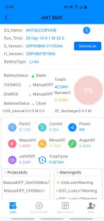
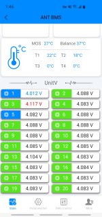
That's a huge variation in cell voltages, given that there is no load on them, just sitting there running the BMS. That's something you typically only see with mismatched cells, which will never remain balanced in use, as they don't have the same capacity or capabilities. So the BMS will have a lot of work to do--the harder the pack is used, and the closer it is brought to full or empty, the more of a problem it can be.

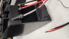
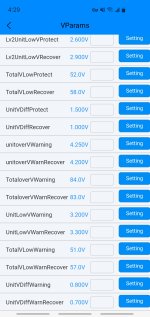
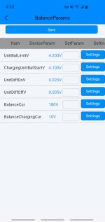
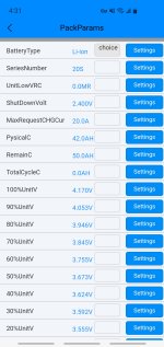
I don't see anything that shows us what your settings are actually at, or what settings you have available to change (and no model info to see what the manufacturer site might say), so I can't suggest any specific changes to make from what they are at now. I have some general info below that may help you figure that out, though.


Pete's moto said:
I was told by Electro Co. that the qs 138 70h with the em260 controller needs a pack capable 400amps or even 450amps if the controller is liquid cooled so yes these are my target numbers and correct me if I'm wrong but the pack could handle this.
Are you liquid-cooling the controller, with a system capable of getting rid of the heat fast enough to make that effective in your specific usage? If not, then you'd be reducing the current limit to whatever it is meant to handle in your usage, with whatever air-cooling you have setup in the build.

To verify that the cells can handle whatever you're needing, you look at the per-cell current capability, x the number of parallel cells.

Molicel's data sheet
https://www.molicel.com/wp-content/uploads/INR21700P42A-V4-80092.pdf
View attachment INR21700P42A-V4-80092[1].pdf
CELL CHARACTERISTICS
Capacity
Typical 4200 mAh
15.5 Wh
Minimum 4000 mAh
14.7 Wh
Cell Voltage
Nominal 3.6 V
Charge 4.2 V
Discharge 2.5 V
Charge Current Standard 4.2 A
Charge Time Standard 1.5 hr
Discharge Current Continuous 45 A
Typical
Impedance
AC (1 KHz) 10 m
DC (10A/1s) 16 m
Temperature Charge 0°C to 45°C
Discharge -40°C to 60°C
Energy Density Volumetric 615 Wh/l
Gravimetric 230 Wh/kg
shows a 45A continuous capability, but they only graphed up to 30A in the discharge curve, so until you use it like that (and monitor the cells) you won't know what kind of voltage sag (or cell heating), they'll have at that rate. THey dont' sag hugely even at 30A, but 45A is 1.5x that much, so they presumably will sag at least proportionally worse at that load.

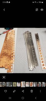
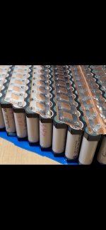
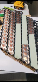
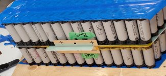
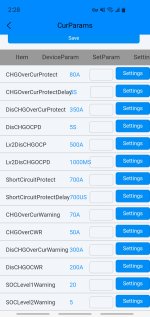
At that rate, a 14p would be capable of 14 x 45 = 630A. I don't know what gauge your interconnects are between the cells, or the cables out of the battery or how they are connected to the pack ends and BMS, but as long as all of those are capable of that kind of current, then the pack could do this and remain within the cell limitations--but it would be pushing it very hard. It would also only last 0.08 hours at that rate, or about 5 minutes.

400A is not pushing it nearly as hard, at only 28A/cell. At 400A continuous, the pack would only last about 8 minutes or so. Presumably you wouldn't be using it at that rate very often, though, so it could last much much longer in actual usage, depending on how hard you push it and how often.


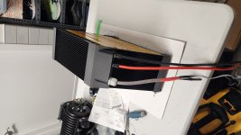
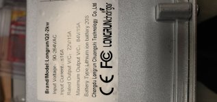
Personally, for that kind of current, I wouldn't use a BMS with FETs controlling charge/discharge, I'd use one with a contactor instead (less waste heat to deal with, less chance of a stuck-on failure, etc). I don't know what your specific model's specs or capabilities are (don't see any model number in the thread or I would find them from the manufacturer site if they have that info there).

Depending on the heat that could be produced, if it does have FETs (which depends on their actual RDSon vs temperature and the current at the time), I'd go ahead and actually bolt it's heatsink to the pack heatsink/case, with any labels that are on the BMS heatsink plate removed so it has full complete surface contact metal to metal. Better yet would be removing the original heatsink plate and directly bolting the BMS to the case's heatsink plate such that the FETs all have good direct contact to that plate; there are less thermal barriers and lower thermal resistance to get the heat out of the FETs that way.

If there's no significant heat generated in the BMS at the currents being used, that's not necessary.


Yes i want to be conservative and would like this battery to last, yet it wont be my day-to-day ride its more like a toy using it occasionally but when i do i like to have the power and performance.
For those conditions, then you might as well use the cells as hard as you like--they may degrade from calendar aging before hard usage does them in. ;)

So given the cell specs from manufacturer, you could set a current limit below the 630A but above the max the controller will ever use in your specific usage (which might not be anywhere near the max it's capable of).

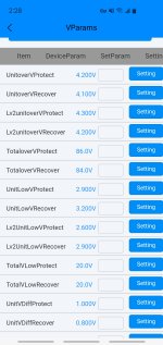
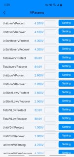
The HVC of the cells themselves is 4.2v. If you need the most capacity (riding time) from the pack then you would want to charge as full as possible, otherwise you could use a lower HVC (which reduces stress over time, but also capacity), say 4.0 or 4.1v.

The LVC is 2.5v, but there's so little energy down there that using 2.8v (typical LVC) doesn't lose much; even 3v won't make that much difference.

At 4.2v-2.5v, assume you'll get about 4Ah out of each cell, or around 56Ah out of the pack. At 4.0v to 3.0v, assume you'll get about 3.2Ah, or around 45Ah. Depending on cell condition, how well-matched they are, and actual current draw, you may get more or less than that.

Remember also that the BMS LVC is a cell-level thing, intended to protect against overdischarging a cell. The actual everyday functional shutdown LVC is in the controller, and that is often set to 3v/cell or higher, so for a 20s pack that'd be 60V or higher. Some controllers also have a "pre-LVC" that reduces the controller current limit as the voltage reaches that point, so it doesn't cause as much voltage sag on the pack so it won't shutdown early--it just reduces the power capability of the system.
 
Here some pictures of the ant bms and some pics of the method i used to build the pack
Feel free to point out any comments
It might be to late to do any changes to the pack as is done sealed and closed.
 

Attachments

  • Screenshot_20230115_141202_Gallery.jpg
    Screenshot_20230115_141202_Gallery.jpg
    972.2 KB · Views: 163
  • Screenshot_20230115_141607_Gallery.jpg
    Screenshot_20230115_141607_Gallery.jpg
    1.1 MB · Views: 164
  • Screenshot_20230115_141412_Gallery.jpg
    Screenshot_20230115_141412_Gallery.jpg
    775.8 KB · Views: 164
  • Screenshot_20230115_141519_Gallery.jpg
    Screenshot_20230115_141519_Gallery.jpg
    1.4 MB · Views: 164
  • Screenshot_20230115_141438_Gallery.jpg
    Screenshot_20230115_141438_Gallery.jpg
    1.5 MB · Views: 165
I only changed things in the fast settings actual number of series, battery type and physicalC.
The rest of the parameters i think they set by default by manufacturer and as per his advice it is not necessary to set(I doubt it)
Also was instructed to turn off discharge/charge MOS before connecting to load and charger.
As per my understanding i need to charge the pack first and balance after so thos might be the reason for the voltage differences between the series.

Thank you all for the help
 

Attachments

  • Screenshot_20230115-142823_ANT BMS.jpg
    Screenshot_20230115-142823_ANT BMS.jpg
    501.9 KB · Views: 166
  • Screenshot_20230115-142833_ANT BMS.jpg
    Screenshot_20230115-142833_ANT BMS.jpg
    548.2 KB · Views: 166
  • Screenshot_20230115-142857_ANT BMS.jpg
    Screenshot_20230115-142857_ANT BMS.jpg
    511.5 KB · Views: 165
  • Screenshot_20230115-142917_ANT BMS.jpg
    Screenshot_20230115-142917_ANT BMS.jpg
    480.9 KB · Views: 165
Pete's moto said:
As per my understanding i need to charge the pack first and balance after so thos might be the reason for the voltage differences between the series.

Some thoughts for consideration; I can't know if they are applicable to your situation; hopefully they are not:

When you get the cells, if they are all well-matched in characteristics, they should start out the same voltages, because they should have seen the same environmental conditions, and same starting conditions from the factory, and the same aging, etc.

If they aren't all the same / not well-matched, they won't all behave the same in-use, and will age at different "rates" in different ways, becoming less-matched over time, requiring more work by the BMS to keep them balanced.

Balanced (top or bottom) only means they are all at the same voltage. It does not mean they are at the same capacity or capability. But an imbalance usually indicates a difference in those things between the cell(groups) that are different from each other--the larger the imbalance, the greater the differences in cell properties / capabilities.

Normally "balancing" would be very small differences (a few hundredths of a volt). Some BMSs won't even allow charge or discharge if there is greater than a tenth of a volt difference between cell groups, as that can indicate a serious fault in the group with that much difference (failed cell or interconnect, etc).

If this BMS is like that, then you'll need to manually balance the lowest or highest (or both) before it can be used. Whether the BMS itself can do the job in that state depends on the BMS design/software.
 
Pete's moto said:
The rest of the parameters i think they set by default by manufacturer and as per his advice it is not necessary to set(I doubt it)
Assuming the parameter names in the screenshots mean what they say they are, then the main things I see that you could change (but probably don't need to) are:

TotalVLowProtect could be raised to whatever you want to use for the cell level LVC x number of series cells. Then the TotalVLowRecover to whatever you want the pack to turn back on for if the voltage rises back again above that point when the load is removed. Most likely these would match the per-cell voltages of the regular LVC Protect/Recover parameters, x the number of series cells.

There are also Warning parameters for the low end like above, so you could change those to appropriate relative voltages as well.


I see a parameter for UnitVDiffProtect, that is likely the difference allowed between cells before the BMS shuts down charge/discharge. The recover would be for what the difference must be reduced to before it will re-enable those. If this is the case then you could temporarily change it to something greater than the present maximum cell difference, so that you can charge and balance, but remember to change it back before using the pack, so taht it will protect you against the problems it is intended to.

The DiffWarning parameters you should be able to leave alone.

The rest of the parameters look safe enough.

For the discharge currents, you need to set those above what your controller's current limit is, but below the maximum the BMS is capable of. The label says 400A, so I would make sure there are no current parameters set higher than that, if that is actually what the BMS can really handle safely.

If your controller's current limit is higher than the BMS capability, you need to change the controller current limit to be below that, for all places it has a limit, both peak and continuous, so you don't damage the BMS, or experience shutdowns because the BMS is protecting your pack against overcurrent.

For the charge currents, you need to set those based on what charge currents you intend to use, vs what the cells and BMS can take. Spec sheet says 4.2A max per cell. Make that a round 4A x 14p and you get a max of 56A charge rate.


There's a field for total pack capacity, and some SOC parameters probably based around that. You can look at the discharge curve on the Molicel sheet to see how much capacity per cell you get based on the HVC and LVC you choose in the BMS, vs the current draw you expect to use on average. Multiply that x 14 for the expected capacity of the pack, and put that in that field. 42Ah is what's there now, and that's probably reasonable given the present other settings, if you want to leave it as-is.
 
amberwolf Thank you
As per your instructions
There is balance parameters and pack parameters.
Is balancing done automatically or manually?
Also a picture of the charger
 

Attachments

  • Screenshot_20230115-162943_ANT BMS.jpg
    Screenshot_20230115-162943_ANT BMS.jpg
    523.5 KB · Views: 154
  • Screenshot_20230115-163010_ANT BMS.jpg
    Screenshot_20230115-163010_ANT BMS.jpg
    510.7 KB · Views: 154
  • Screenshot_20230115-162948_ANT BMS.jpg
    Screenshot_20230115-162948_ANT BMS.jpg
    546.7 KB · Views: 154
  • Screenshot_20230115-163039_ANT BMS.jpg
    Screenshot_20230115-163039_ANT BMS.jpg
    270.8 KB · Views: 154
  • Screenshot_20230115-163121_ANT BMS.jpg
    Screenshot_20230115-163121_ANT BMS.jpg
    525.3 KB · Views: 154
  • 16738185925354900177374692586860.jpg
    16738185925354900177374692586860.jpg
    1.9 MB · Views: 153
Pete's moto said:
There is balance parameters and pack parameters.
Is balancing done automatically or manually?
I don't know that brand of BMS well enough to say; you'd have to check it's manual to see. Or check the big thread(s) that include a lot of info about the ANT brand.

But most BMS exist specifically to do everything automatically.

And most programmable BMS do the automatic things based on the settings programmed in.
 
I charged the battery a few nights ago and has been balancing since. This is how it looks now, i hope it only get better. I had to initiate automatic balancing in settings.
Thank you for helping i think i get it now at least this part of my project.
I will start a post of my conversion in the motorcycle section hopefully I'll help and suggestions there too
 

Attachments

  • Screenshot_20230119-134633_ANT BMS.jpg
    Screenshot_20230119-134633_ANT BMS.jpg
    503.2 KB · Views: 102
Back
Top