APL's Pressure Contact Battery box

I have a ton of already plated busbar in the perfect dimensions. 32mm x 1.3mm x 2000mm.... Strip from Flexibar flexible wire busbar. I sell for 10$ A POUND. Got 100 lbs. Erico Flexibar.

i COULD SEND YOU A STRIP TO SEE IF IT TESTS WELL FOR YA.. iT IS VERY VERY HIGH QUALITY PLATED BUS.

SRRY for shouting. Caps lock has a mind of its own.
 
john61ct said:
Sorry Dog but exactly what are the materials of that buss?

We have a bout a ton of Erico Eriflex Flexibus from a nuclear plant. Flexible busbar.. is commercially sold as layers of copper ( nickel plated, spec) in a rectangular section that flexes.

I cut the black insulation off and use it for battery building.I bough 10 lbs of it last, each bar is 25 lbs.. the 2" ones.

The 1.3" ( wide strips) ones are about 18 lbs. Contain (8) layered strips, the 2" ones are the same.. but wider.

Cheap. Copper. Plated and already cut to dimension. The ones I dismantle are 2000A continuous bus and 2800A continuous. We got about a ton.

You have probally seen it.. I stamp and cut my interconnections with it. The little plates I punch, stamp, fold, and punch again... for the cell pouch connections.. Its alot easier to chop to spec and longer lasting. I built a pack with untreated copper and it got tarnished.. still worked but was tarnished upon dissassy ... a year later.. Teh nickel plated stuff is great, two years later and nary a bit of non shiny buss... Professional plating. No tarnishing. One (5$) strip does a whole battery for me.. I bought ten.

https://www.erico.com/category.asp?category=R2028

I am actually building a plexiglass case that takes the strip for easy .. connection manipulations. Built in swappable, boltable, terminals so you can change a battery from 12s to 24s easy on the fly. Depending on whether you have a 6" strip interconnecting or a 12".. switching... .. Sorta. Stay tuned.

I punch it stamp it cut it, ect. It is .039 inches thick.. very easy to manipulate ( 1 mm-ish) ( 1mm x 32mm )( 65 kCmil) , for my smaller stuff, or, 1mm x 51mm , for the heavier 2" wide (133 kCmil) .

Its like a 2 gauge, ( smaller stuff) or 00 gauge, ( wider stuff) wire but solid, flat, and plated, designed for flexing in applications. .


Its good for EV.


Thin layers of tinned electrolytic copper formed into a stack
Full range from 19.5 mm² up to 1200 mm² and 125 A to 2800 A
Insulated by high-resistance, halogen free, flame retardant and low smoke material with less than 20% contact with conductor for high flexibility
Easily bent, folded, and twisted, improving assembly flexibility, shortening connections, and decreasing footprint
Dramatically smaller and more flexible than comparable cable based on ampacity
Better power density than cable with lower skin effect ratio
Connections made by punching and bolting directly through the copper laminates or clamping onto the end of the nVent ERIFLEX Flexibar
No lugs needed, reducing installation time and improving resistance to vibration
Weight savings and material savings compared to wire alternatives
Reduces total installation cost
Traceability codes and designation part numbers printed on insulation
Conforms to NF EN 45545 obtaining an HL2 classification for chapters R22 and R23
100% production dielectric tested
RoHS compliant
Tinned copper allows for copper or aluminum conductor connections
On request, can be manufactured with other colors (typically with Orange sleeve for battery connection)
Compliant to ISO 6469-1 (Electrically propelled road vehicles - Part 1: Rechargeable energy storage system) - Section 6.2.2 Vibrations
 
Wow glad I asked, looks like a fantastic system.

LOL what sort of connections did you make to buy surplus gear off your local nuclear power plant?
 
john61ct said:
Wow glad I asked, looks like a fantastic system.

LOL what sort of connections did you make to buy surplus gear off your local nuclear power plant?

OMG if you only knew. What I have seen scrapped. I get mad. Lol.

Dad is (was) a nuclear engineer. So we see this stuff. Powerplants have notoriously large and powerful back up power systems and whatnot ( large busses, to power huge diesels and other electric machinery, ect.. Huge battery rooms filled with lead acid batteries, ect.... Stainless piping for miles, all very expensive when installed but scrap now ) and our Mennonite friends scrap it and let us root around in it. We get to buy whatever really at cost. Spend alot with them. They even let me use the XRF gun. Lol .

I am thinking about selling the bus bars straight off eBay even with the ridicoulus 12.55% fee. Lol.
 
Wow DogDipstick, super interesting stuff! I'd give my left nad to dig around in nuc-scrap like that! :)

The bus bar sounds like really nice stuff, but a little on the thick side for this project at .039",.. I'm using
.025" at the moment and thinking I might need even thinner. But, I have a ways to go yet, so I still might
take you up on it. The 32mm width is perfect and the nickel plating is awesome!

I need some flexibility in the copper between each dimple to the next, but it's just guesswork at this point.
once I get further along I'll know more about that. (hopefully)
The whole pack depends on being able to make up for any differences in cell lengths & component parts
for each set of contacts. Probably only 1mm or so at most, but still necessary.
 
Thanks for the info stan.distortion, awesome link! That's a real good start, and I'll have to do some more research
before I get into it, but it doesn't look 'too' hard. I've had some experience with anodizing aluminum, and know
how difficult plating can get,.. (boy do I know), but persistence seems to pay off.

I've got a little ways to go yet before I need to get into that, but need to keep thinking about it.

I managed to at least get the dimple holes drilled into some .032 FR4 Garolite glass board, all 192 of them. Would
have been easy with a laser cutter, or water jet, but I did it on the little drill press with a nitride step drill. Worked
out pretty good in the end, but very monotonous. Gee, I only have to do it once more. :roll:

The sheet turned out stronger than I thought though, so I'm happy with that, and the board is pretty high temp, so
this should work out well.

Insulator sheet.jpg

The strip is a little too wide though, so I guess next up is to make a full strip of copper with all the thru-holes in it,
and see how it fits and flexes.
 
Another well done thread APL :bigthumb:

I was going to 3D print modules and buy that popular hardware kit to make battery packs, but I may try something like you are doing instead.

I can make some stamping dies using my mill and lathe BUT if I am already going to order 3D binder jetting printed coils and motor buss bars I may consider designing and printing battery buss bars too. I like the idea or having solid pins that protrude from a thick narrow bar versus punched copper plates. Such bars can be spray coated with dielectric coating and then dropped into a 3D printed endplates which are then potted. This then becomes backed by poron foam.

I share a similar climate and winters, and am not a winter cycling advocate, so I share your desire to safely decommission large battery packs by opening the pack and removing cells for winter storage. That or using low capacity LiFePo4 cells. I had a scary episode with RC pouch battery, that was enough for me.
 
3D printing copper SP strips would be trick if works,.. best way yet! :thumb:

Well, like I say, I don't know if this is going to work yet, I can still see some issues and unknowns. One is that the
final bus bars on the ends will need to be thicker copper than the strips. I'm hoping extra thru bolts there will
fix it, (should probably be more pressure there anyway, since that's where all the current will be.)

Anyway, I'm becoming quite the dimple-master,.. I've managed to get three of the strips done, and it's getting easier
as I go. They seem to be able to flex alright, but it does take a bit of force. Got my fingers crossed.
There's about 10mm of .025" inch copper between the center holes, so it should handle current fairly well.

Full SP strip.jpg

The sides of the strips will need to be relieved for the thru bolts yet, which will have a hard nylon tube around them
where the strips are.

For added safety, the plan is to add some fiberglass dowels to the compression plate sides, that fit in between the
strip-sets and keeps them separated.

There's another sheet of .032" FR4 board that gets bonded to the backs of all the strips with some RTV.
 
For the dimple maker to be reliable you need to secure copper sheet so it does not move and rather stretches copper into dimple. Her is my first crude dimple maker:
upload_-1.jpg

and the reseult:
upload_-1.jpg

After i revised my design, went for second dimple maker, this time more professional with clamps for quicker action:
PnDnGFD.jpg

and the result:
[youtube]rOGFEVZOwe0[/youtube]
Then just ordered dies to press them.
 
Awesome tool agniusm! And nice video as well, very professional and precise looking operation. :thumb:
Your getting really nice parts, and it's really nice to see somebody else that's doing this kind of thing.

Just visited your web site and really like what you've been doing with the module, really cool set up, and
I'm probably biting off more than I can chew with a 16/12 pack to say the least. I was surprised to read about
your experience with nickel plating and the resulting brittleness,.. hmm, might have to rethink that deal.

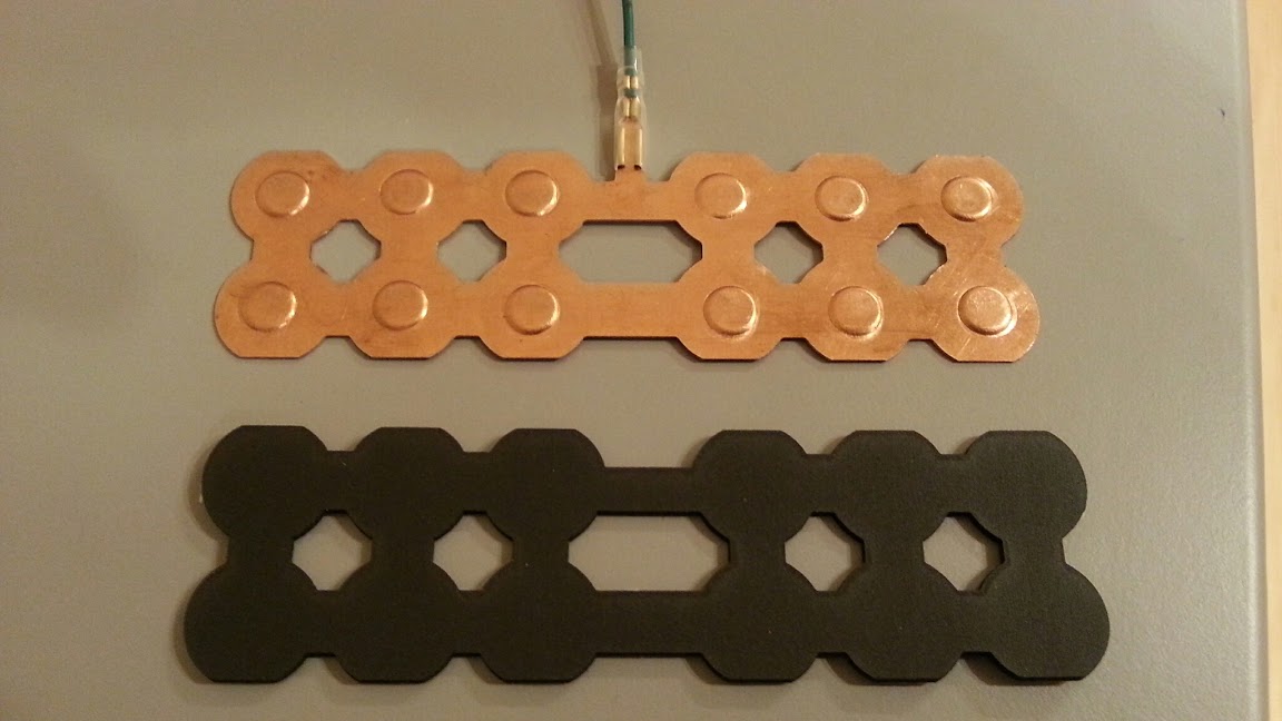
The dimples I'm making are a bit deeper than yours, to reach through the FR4 board, and tend to draw in the
surrounding copper a little I've noticed. In fact I use a light oil on all the parts to allow for this to happen.

I think if I clamp the copper on top it might lead to ripped dimples in this situation, could be wrong, but just
going back and forth with the hammer to keep the top flat seems to work well enough so far, I can't complain.

Dimple height seems to be consistent enough, and I'm hoping that the Poron will make up for any slight
differences. There's a lot of hope going on though, so once I bolt it all together I may have to walk this all back
a ways,.. :confused:

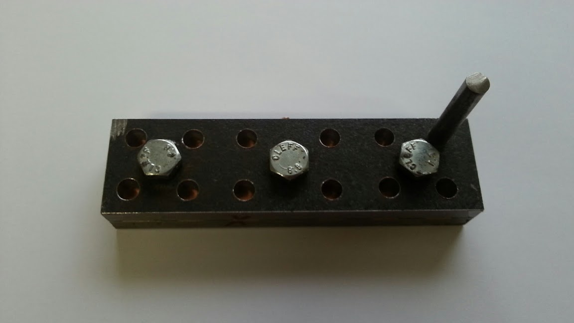
If I was going to make more than one battery I would definitely think about making a press ZeroEm, but I'm
not sure about the stop part since the punch has to hit something hard behind the dimple, unless I'm missing
something,..

I know that stan.distortion uses cap screws so that he can adjust for dimple heights, which is a nice option.
 
I'm on the edge of my seat thinking about making a 16s 16p battery would really be a two 16s 8p in parallel. So don't give up I don't want to weld and will need to come up with my own invention. :lol:

Good work.
 
For sure mine is shallow at .6mm. Perhaps slightly thicker copper might mitigate ripping? I guess its trial and error approach :)
 
I admire building your own batteries, but it seems like spot welding is being viewed as more permanent than it actually is. I've abused one of the five batteries that I've built so far (the one for my bike of course), and it hasn't been that hard to make repairs. Four times now I've scraped or pulled the nickel strip off, slide the cell out, and weld in a new one. The other four packs haven't been abused, and since they're built with new batteries they're all still balanced very well and have never needed to be touched.

The copper stamping seems to be APL's style, so have at it an see how it turns out! Don't be afraid of spot welding though; people rip apart packs to salvage cells all the time!
 
Well that's what I was thinking about last night, seems to be a chicken and the egg thing going on, these cells are
welded most of the time, but they weren't really designed for that in the beginning were they? I would think
there would be better provisions for welding nickel strips too, than a flat bottom and a button top.

Plenty of places where they're used in compression/series mode, like laptops or a flashlight set up,.. so was that the
original intension? Just a thought.

Anyway, I don't have all that much against welding, nice and quick, light, compact and strong. And if your taking apart
and welding again, it all works out I guess, after all, these batteries don't last forever.

But you know me,.. I have to do everything different, and take the long way home. :wink:

If I ever win the lottery and buy all new 'top shelf' cells, I think I'd have a hard time taking a welder to them. And the
compression box I'm making should last a long time, hopefully several bikes, (might be wishful thinking there).

It is a royal pain to make though, and I can't talk about the attributes to much until the damn thing is working, so cross
your fingers, cross your hart, and cross anything else you got,.. (just in case). :lol:
 
I'm getting about the same way with the welded cells. Tried to stay away from building batteries but being drawn into it for shape and voltage of the battery needed. Read some of Luke's post about welding batteries. That has turned me away from it.

I know welding is the easiest path, know some of the issues of compression batteries. Still i'm persisting on a no weld build.
 
Personally I think the ability to quickly atomize the parallel groups, run them through a sorting hat battery of tests (hehe) for capacity and resistance

then easily reassemble the pack(s)

is critical.

Not to mention being 100% sure no longevity shortening going on from heat penetration, when we're talking thousands of dollars in new top notch cells.

No need to buy and setup a welder.

I am confident we will get there.

N. E. S. E. seems a great concept, just needs more flexibility

with CAD/CNC/3D printing becoming more and more commonplace

such crowd-sourced prototyping will pay off.
 
Hmmm.. my first blunder, it's the old measure it once & build it twice thing.

Thought that I made the frame with a 10" hold, but it turns out to be more like 9-3/4" ish. The battery itself needs to be
a little wider on the back side for the internal charge and power wires to run, so between those two things I've run out
of room. There's also the two 3/16" sides that need to be bonded on, and suddenly it's just to tight.

ASS-U-M-E. :roll:

Battery fit (1).jpg

OK, so it looks like I have to take one row of parallel cells out and make it a 16S/11P pack. Unfortunate, but no biggie.
Hacksaw, belt sander, done. Best to catch it early,.. turn the page.

Anyway, I've just been working on making all the parallel strips and have the one side of 8 done, and I'm just starting on
the other side. This batch will be a little easier since there's no need for the center holes because they won't need to flex,
and will be bonded directly to the compression side plate.

Not all that much progress because this time of year is all about putting things away and getting things ready for the winter
months, which takes up most of the time these days.
 
My idea is leaving enough space between the cells to run the internal wiring between them

Also good for cooling if needed.

I'm thinking each cell has its own pair, use waterproof plugs to the outside

then use a separate wiring box to make the xPyS layout

still leaving access for the BMS to be pulled / replaced

future monitoring, balancing etc done by whatever gear I want.

And each cell showing up as a weak link easily replaced, without physically atomising the whole assembly

just a thought experiment for discussion.
 
That's a pretty cool idea john61ct, would need a printed cell holder that allows for wires, maybe threaded caps on the
outside. A separate box for the P/S and BMS is unique, and allows for some nifty switching options. :thumb:

I'm going to try to place the BMS on the outside too. I'm not sure exactly how that's going to go down yet, but have
some ideas. Ideally, the BMS should be exposed to the outside air, with a finned aluminum heat sink on it, since it's a high
amp circuit.

The problem comes with all the wires, and the need for plugs that can withstand many connection cycles. That little
17 pin BMS strip is only good for a few times, so there will need to be some mid-plugs, plus some main power plugs,
and enough room for all that.

At the moment I'm thinking 4 of those mini 5 pin XLR/Hall plugs, but I haven't really researched connectors much yet.
 
Yea, the Deutsch multi-pins look like the ticket, I'm sure I can find a combination that will work there. Thanks!

I guess I have to accept the fact that this battery will be charged in the frame and not taken out, (like I do now).
I've charged in the frame a few times, but I don't like doing it,.. something about watching my bike go up in smoke.

I usually take the battery out and put it in a metal box outside to charge it.
(I refuse to charge inside a building.. just the way I roll I guess.)

Problem is, the weather outside isn't always charge-worthy, so I always have two batteries that I alternate back and
forth to overcome that.
If I 'have' to charge in-frame, then the bike has to be outside. So I guess I need to make a special place for that.

Anybody else know this problem, or am I just being one of those guys ??? :?
 
Yes best to charge where a small but very intense fire could be allowed to burn out and the smoke/fumes would do little harm.

A small metal shed in the middle of a back yard would be ideal.
 
thundercamel said:
I admire building your own batteries, but it seems like spot welding is being viewed as more permanent than it actually is. I've abused one of the five batteries that I've built so far (the one for my bike of course), and it hasn't been that hard to make repairs. Four times now I've scraped or pulled the nickel strip off, slide the cell out, and weld in a new one. The other four packs haven't been abused, and since they're built with new batteries they're all still balanced very well and have never needed to be touched.

The copper stamping seems to be APL's style, so have at it an see how it turns out! Don't be afraid of spot welding though; people rip apart packs to salvage cells all the time!

In my case it welded nickel strip simply wouldn't handle the current. 10mm x 0.3mm is good for around 30 amps before losses and inefficiencies start getting significant and that's the max continuous rating of the 26650 LifePO4 cells I'm using but similar cells are readily available than can push over 100 amps so if I ever want to up the current then welding nickel strip simply isn't an option. Welding copper strip with nickel patches looks like it's proving a good option but being able to disassemble a pack is a big plus for me at the mo, making it work reliably for years on end will no doubt be a challenge but I'm certain it's possible while sticking to hobby level tech.
 
Back
Top