Connecting different Switching Power Supplies in series?

manfred59

10 W
Joined
Jan 7, 2008
Messages
72
Location
AUSTRIA
Is it possible to connect two ore more Regulated Switching Power Supplies in series?
In my special case I want to connect a 36V DC 9.7A 350W PSU with a 12V DC 18A 250W PSU to get a voltage of 55V or better 56V for charging a a123 / 15s battery. If it is possible which current would be realistc?
 
You would only get 48V by putting these two in series.

And the maximum current would be limited by the specs of the unit with lower current output, therefore 9.7A.

The max power would be 48V x 9.7A = 465.6W.
 
Is there some way to isolate power output if it is not isolated?

That seems to be the problem with my attempts to charge weak cells within a 102 cell string with the juice left in the good cells. The outputs of my IMAX B5 charger are not isolated from the negative input cable voltage.
 
Yes, you can isolate it, but the details depend on the charger.

All switching mode power supplies have a input (hot) side and an output (secondary) side that are inherently isolated. If you take apart the charger, you can see the transformer and optocoupler that separate the two sides. So there has to be some kind of connection from the AC ground pin to the secondary side that needs to be cut. It's safest if the ground connection still goes to the parts on the hot side (usually the transformer frame and heat sink), but cut the connection to the output side.
 
Aaah.. I can see another warranty biting the dust! I'll have a look in there!
 
I went a bit too far and let the magic smoke out the IMAx B5.

This is how I connected it when it fried:


Before frying it, I wrote this draft but did not post it:
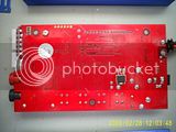
I've opened the IMAX B5 charger up and had a look and did a few resistance measurements.

There seems to be a resistance of 10MOhm between the input leads and the output leads. But I did a few weeks ago measure that there was the full voltage between the negative input lead (plugged into a tab of the 102 cell string) and any other cell in that 102 cell string. There was also a spark when I first tried to connect one of the two output cables to the tab of the cell I wanted to charge.

The IMAX B5 PCB is way too complex for me to understand. It has a top and a bottom layer, and loads of very small components. Additionally, many parts cannot be inspected easily because the LCD display has been mounted over the top of the smaller components at the end of assembly.

My guess is that the spark was caused by a discharging capacitor, and that the current flow after that initial spark would have been negligible, apart from the actual charging current once the charger is starting to charge.

I'll try to take some more measurements later on. Maybe measure the current flow between output leads and 102 cell string tabs through a resistor; that should show if the sparking is a temporary current or a true short circuit.

I did make more measurements instead of posting the above: The resistance values kept changing, depending on polarity and duration of connection to various points on the IMAX PCB; due to capacitors, I guess. And the resistance values between power supply cables and output was always in the several MOhm range, usually 8 - 10MOhm.

So I thought it might be safe to try it out....Not So!


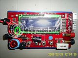
Excuse the poor picture quality, please:


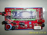
I connected the Input cables to tabs 3 (+) and 11 (-) of the 102 cell string (still counting the wrong way from the positive end up...) and the IMAX fired up as it's supposed to.

I measured voltage between positive and negative output cables and tabs 1 and tab 2: Very close to what it would have been between tab 11 and tab 1 or tab 2.

Then I connected an ammeter, in series with a 5W6k8 resistor, between negative output cable and tab 2: About 0.9mA flowed. Very similar results between the positive charging output and tabs 1 and tab 2. When the negative output cable was connected to either tab 1 or tab 2 the charger would give an error message: "Polarity error"

When the positive cable was connected to either tab 2 or tab 2, then there was no error message.
When the positive cable was already connected to tab 1 , then there was no error message when the negative cable was connected to tab 2. The current flow was still below 1mA, still with the 6k8 resistor in series.

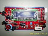
Then I set the IMAX to charge at 1A and pressed start. It announced that it is putting in exactly 1.5A, and at about 12V, into a single cell. The ammeter reported something between 1A and 1.5A. I turned it off and on again. Same result.

The I realised that the 6k8 resistor was still in line (and very hot). I removed it and repeated the 1A test. I got an "Input voltage error", and put the negative input terminal one tab higher up on the cell string to increase the input voltage. When I turned it back on, there was a slight POP and smoke came out of the side of the IMAX.


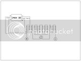
The small, 8-pin IC that smoldered is circled in green:
 
The IMAx B5 looks like a buck regulator, not a transformer based switcher. I don't think there is a way to isolate the input and output on one of those.
 
Thank you very much!

I'll try to get a replacement part for the fried switch (???). That will be a challenge to solder that in, it will be the smallest solder joint I have attempted so far.

The IMAX B5 has been quite reliable and useful for me, but I dislike the maximum capacity cutoff of 9900mAh and the maximum timer cutoff of 720min = 12 hrs. That does not make sense for charging 30Ah NiMH cells, which should be charged for 15hrs at C/10 or thereabouts.

Does anybody know if a switchmode battery charger with fully isolated output is available? One that can be powered by about 18V DC? Even a power supply might be sufficient, I don't need -dV/dT detection or such fancy stuff when I just need to shift a few amp hours within the pack to make it home.
 
fechter said:
The IMAx B5 looks like a buck regulator, not a transformer based switcher. I don't think there is a way to isolate the input and output on one of those.

What baffles me is that I vaguely remember something about transformers only working for AC - but I might be completely wrong there.

Or do fully isolated DC/DC converters turn DC into AC first, then put the AC through a transformer, and then turn it back into the desired DC voltage?

Anyway, I could not find a replacement for the fried part yet, but was able to have a look at a new IMAX B5 to read the writing on the fried part:
It's says:

IOR P529H
L28F
F7424


The guy in the shop told me it's an SCR ("Whats a diode with a third leg? - an SCR!")
That probably stands for "Silicon Controlled Rectifier" .

Anyway, I might one day understand how to source (and fit) the correct replacement part, until then the IMAX B5 joins the growing pile of electronic treasure in the garage.

I bought a new charger instead to keep going in the meantime: Not cheap for AU$169.- , but it included a 100-240V to 12V (6A) power supply! That one is probably an isolated switch mode power supply.

The charger is called: RT-808D (no brand name I could find)

http://www.nem.gr/rt-808-p30058.html

I have not had time to test it yet, but it claims many more features than the IMAX B5 has. Most notably discharge function with selectable current and cutoff voltage; and automatic cycling of NiMH and NiCd cells.
The negative delta-V is also adjustable, and it comes with multiple adapters, temp sensor, and a USB connection cable.
 
Back
Top