oldswamm
100 W
This project is for ALL ebike electronics except the controller itself. When I finish my controller project it will be both hardware and software compatible.
I've been working on this for several months, and it's quite complicated, please read or at least scan it patiently.
If anyone is interested in this project and would like to help, especially with the software, please PM me (I would like the whole project to remain open source if possible). Also if anyone is interested I can post schematics and PCB drawings. (also note that these PCB designs are for hand made boards. With plated through holes I would redesign.)
The reasons for doing this design:
Programmability!
Minimize wiring.
More sophisticated (programmable) control for multi wheel drive.
Better current monitoring with multi wheel drive.
Safer and more useful 3way switch operation.
Temperature based current limit and/or shutdown.
Speed based cruise control (could have it's own current limit).
Auto sensored/sensorless switching.
Self calibrating for the Hall and sensorless inputs.
Anti spin. Anti wheelie.
True programmable wheelie control would PROBABLY be possible.
Eventually anti skid and anti flip braking (AFB?).
Will describe each board individually. All, except the in hub units, use the same serial interface, which allows 3 wires for most of the bikes wiring, (12V, ground, and the serial line). Would put taps anywhere I think I might stick another board.
Head unit (mounted to the handlebars, or in the cowl):
 (Note, the buttons should be below.....) It also could use one LED array instead of the 2 as drawn.
Uses a PIC 18F46k22.
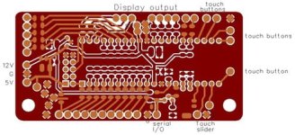
I don't have a schematic for this board. A standard 5V regulator. The outputs to the display have current limiting resistors. The I/O have provision for current limiting and an optional pullup resistor. Touch buttons are direct. Here's the serial I/O. I haven't decided on the speed or current, which will determine the resistor and cap values. There's a voltage divider in the input to the CPU to set the thresholds.
View attachment 3
This boards primary purpose is to interface controls and the readout to the rest of the system, but it would probably be 'the brains' as well. As designed there are provision for up to 17 Inputs (or outputs such as an LED?), for throttle(s), 3way(s), pots, light and turn switches, key(s), or?. This doesn't include inputs from 7 capacitive touch switches, 5 buttons (esc/1, menu/2, L/3, R/4, enter/5) and a capacitive slide (up, down (will work as buttons or like a pot), the connection to an iButton socket, or the connections to an LCD or LED array (I want a 10"X2.5" red-green-orange display using 'moving sign' type segments, for better visibility under harsh conditions).
I intend to use iButtons both for keys (could use different keys for different performance limits), and also for data log transfer. Changes to the programmable parameters could be 'programed' on a PC then transferred with the iButton. Parameters could also be changed in the field with the head unit buttons. RS232 or USB could be options, if.....?
There's also a separate board on the other end of the display (not pictured), with a mosfet switch, diode isolated for 2 '12V' sources, to control power to the LED array and most other boards, and also a TO220 5V regulator for the LED array.
Controller controller:
Uses a PIC 18F26k22.
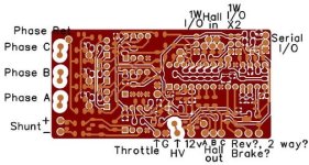
I haven't found and transferred most of this onto the computer, but here's the phase sense input, which is most likely to draw comment. I can't find the pdf that I got this particular circuit for the virtual neutral point from.....
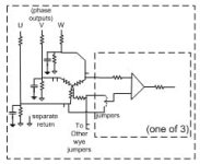
Outputs are current limited. The output to the throttle is double filtered (RC) PWM, then buffered. The shunt has a basic buffer.
(Can't decide what to call this board.) Mounted inside any controller. Inputs for the Hall sensors (or 3 bit parallel, auto select), the phases (for sensorless), the shunt, the serial I/O, and both the B+ and driver supply (for monitoring with ADC). Outputs for throttle, and to the Hall inputs on the controller. I also have 3 more outputs, but don't really think they will be needed (brake, 3way, reverse, lock?). There's provision for monitoring FET temps using Dallas Semi 1wire temp sensors, and a thermistor to monitor ambient/crystal temp (for a temp compensated clock, so I have accurate phase timing outputs for traction control). The phase inputs are jumper selectable for delta/wye, and a daughter board could be used for on the go selection. If none of the 3 extra outputs are used, and no 1wire, there would be connections for 6 offboard thermistors....
In motor board:
Uses a PIC 18F14k22.
View attachment 5
Didn't bother with schematics for this board, pretty simple and straight forward. Current limiting and pullups for the Halls. A single transistor 'inverter' to turn on the FET. A voltage regulator....
This board is a direct replacement for the board in newer 9C hub motors.
There are inputs for 2 'in winding' thermistors as well as one on board, for ambient temp. Obviously, inputs and power for 3 Hall sensors. There's also a TO220 mosfet to control fans or relays, with provision for current measurement, as well as 6 'tach' inputs from fans. If you wonder about the TO220, remember that this board is designed for 125C ambient. A 3 bit parallel output, which connects to the stock Hall wires. This would probably failsafe to standard Hall output. 12V would come in on the original 5V line (you might go slightly oversize on it and the ground for fans or relays).
The BMS:
Uses a PIC 18F26k22.
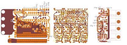
The schematics for the high and low boards:
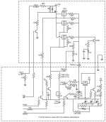
Changed the way the balance current optoisolators interact. (Thought putting batt V accross a 36V part might cause dependability problems.)
Didn't bother drawing the CPU, just labeled lines that connect to it. Most of the unlabeled resistors would probably be 10k, or haven't been determined (depend on the number of cells, etc.) I also reduced the trickle current in the LM317, but didn't relabel it (that resistor would also vary depending on the # of cells). The lines labeled 'chg control' and 'Out control' would be connected to PWM.
The Balance schematic:
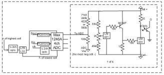
The ADC is basically a block diagram, no PS caps or current limiting resistors shown. I'm using an optoisolator to switch power to the ADC (low current and duty cycle), so don't need a seperate drive to it's CS pin.
The BMS uses 3 different boards. Designed so no one part failure can cause an over charge. (I just 'finished' this yesterday (Dec 4), so it probably has numerous mistakes (statement proven ).)
).)
The board on the low side (negative) has the processor, I/O, output control, precharge resistor, current measurement, and provision for 4 (or more) thermistors. There are ADC chip selects for up to 7 balance boards (28 cell). The chip selects can be used for thermistors if you use less than 7 balance boards. With 5 balance boards there would be 6 thermistor inputs. Measurements for current, batt V, chg V, and the neg output (voltage across the precharge resistor) down to -20V. Includes the multiturn pot to adjust the peak charge voltage.
The center board in the picture is a 4 cell balance board, can use up to 7 of them. Uses a multiturn pot and an LM431 to control each cell voltage by bleeding current through a 13 Ohm resistor. When the shunt current reaches about 200mA, a second LM431 starts pulling current through an optoisolator, all of which are wired-or and used to limit the charge current and notify the CPU of the condition. There is also an optoisolated ADC which the CPU can use to monitor cell voltages.
The third board has the voltage regulator(s), a mosfet so the processor can shut off all charge current, a trickle regulator, and a crude 12V regulator for the 5V prereg, and output fet drive.
They're designed to stack above 5Ah, or larger LiPo.
Boards I haven't designed yet:
Lighting control boards, with or without LEDs. Hall interface boards for suspension and steering position. I might add a board that does nothing but traction control (distributed processing). A tilt and tip board (wheelie control)? GPS? Boards to interface with electric brakes. ETC.....
Software:
I haven't written anything yet, beyond flow charts and some thought to time constrained routines. I like to build the hardware, with provision for future software expansion, then develop the software incrementally. I can't find the software for my programmer, and am waiting for a friend who has the same programmer, but is in Mexico right now, to return.
The project is also stalled because I'm broke. I'm still more than $100 shy of having enough for parts, mostly for the BMS (which is what I really need). Won't be able to do final assy. till I sell something.....
KISS:
For you believers in the KISS principle, PLEASE DON'T MENTION IT. I personally don't APPROVE of the KISS principle. I don't do anything just because it's stupid (when I do stupid things it's at least unintentional). Also note, the main reason for this project is because the commercial electronics is TOO simple.
Actually, I insist KISS doesn't WORK. For example, connect the battery direct to the phase inputs of the motor without a controller (try different connection combinations just in case). Definitely meets the KISS principle, very simple, AND very stupid.
If you can suggest a simplification that doesn't lose function or dependability, go for it, but that's KISP (keep it as simple as possible).
If you have any constructive suggestions or criticisms, please post or PM. (One thing I forgot and just remembered, was I intended to provide for a capacitor paralleled with a high value resistor to provide chassis grounds, in the hubs, to the frame, and to the handlebars...... Can be incorporated in the harness....)
Thanks for reading.
Bob
I've been working on this for several months, and it's quite complicated, please read or at least scan it patiently.
If anyone is interested in this project and would like to help, especially with the software, please PM me (I would like the whole project to remain open source if possible). Also if anyone is interested I can post schematics and PCB drawings. (also note that these PCB designs are for hand made boards. With plated through holes I would redesign.)
The reasons for doing this design:
Programmability!
Minimize wiring.
More sophisticated (programmable) control for multi wheel drive.
Better current monitoring with multi wheel drive.
Safer and more useful 3way switch operation.
Temperature based current limit and/or shutdown.
Speed based cruise control (could have it's own current limit).
Auto sensored/sensorless switching.
Self calibrating for the Hall and sensorless inputs.
Anti spin. Anti wheelie.
True programmable wheelie control would PROBABLY be possible.
Eventually anti skid and anti flip braking (AFB?).
Will describe each board individually. All, except the in hub units, use the same serial interface, which allows 3 wires for most of the bikes wiring, (12V, ground, and the serial line). Would put taps anywhere I think I might stick another board.
Head unit (mounted to the handlebars, or in the cowl):
 (Note, the buttons should be below.....) It also could use one LED array instead of the 2 as drawn.
Uses a PIC 18F46k22.

I don't have a schematic for this board. A standard 5V regulator. The outputs to the display have current limiting resistors. The I/O have provision for current limiting and an optional pullup resistor. Touch buttons are direct. Here's the serial I/O. I haven't decided on the speed or current, which will determine the resistor and cap values. There's a voltage divider in the input to the CPU to set the thresholds.
View attachment 3
This boards primary purpose is to interface controls and the readout to the rest of the system, but it would probably be 'the brains' as well. As designed there are provision for up to 17 Inputs (or outputs such as an LED?), for throttle(s), 3way(s), pots, light and turn switches, key(s), or?. This doesn't include inputs from 7 capacitive touch switches, 5 buttons (esc/1, menu/2, L/3, R/4, enter/5) and a capacitive slide (up, down (will work as buttons or like a pot), the connection to an iButton socket, or the connections to an LCD or LED array (I want a 10"X2.5" red-green-orange display using 'moving sign' type segments, for better visibility under harsh conditions).
I intend to use iButtons both for keys (could use different keys for different performance limits), and also for data log transfer. Changes to the programmable parameters could be 'programed' on a PC then transferred with the iButton. Parameters could also be changed in the field with the head unit buttons. RS232 or USB could be options, if.....?
There's also a separate board on the other end of the display (not pictured), with a mosfet switch, diode isolated for 2 '12V' sources, to control power to the LED array and most other boards, and also a TO220 5V regulator for the LED array.
Controller controller:
Uses a PIC 18F26k22.

I haven't found and transferred most of this onto the computer, but here's the phase sense input, which is most likely to draw comment.

Outputs are current limited. The output to the throttle is double filtered (RC) PWM, then buffered. The shunt has a basic buffer.
(Can't decide what to call this board.) Mounted inside any controller. Inputs for the Hall sensors (or 3 bit parallel, auto select), the phases (for sensorless), the shunt, the serial I/O, and both the B+ and driver supply (for monitoring with ADC). Outputs for throttle, and to the Hall inputs on the controller. I also have 3 more outputs, but don't really think they will be needed (brake, 3way, reverse, lock?). There's provision for monitoring FET temps using Dallas Semi 1wire temp sensors, and a thermistor to monitor ambient/crystal temp (for a temp compensated clock, so I have accurate phase timing outputs for traction control). The phase inputs are jumper selectable for delta/wye, and a daughter board could be used for on the go selection. If none of the 3 extra outputs are used, and no 1wire, there would be connections for 6 offboard thermistors....
In motor board:
Uses a PIC 18F14k22.
View attachment 5
Didn't bother with schematics for this board, pretty simple and straight forward. Current limiting and pullups for the Halls. A single transistor 'inverter' to turn on the FET. A voltage regulator....
This board is a direct replacement for the board in newer 9C hub motors.
There are inputs for 2 'in winding' thermistors as well as one on board, for ambient temp. Obviously, inputs and power for 3 Hall sensors. There's also a TO220 mosfet to control fans or relays, with provision for current measurement, as well as 6 'tach' inputs from fans. If you wonder about the TO220, remember that this board is designed for 125C ambient. A 3 bit parallel output, which connects to the stock Hall wires. This would probably failsafe to standard Hall output. 12V would come in on the original 5V line (you might go slightly oversize on it and the ground for fans or relays).
The BMS:
Uses a PIC 18F26k22.

The schematics for the high and low boards:

Changed the way the balance current optoisolators interact. (Thought putting batt V accross a 36V part might cause dependability problems.)
Didn't bother drawing the CPU, just labeled lines that connect to it. Most of the unlabeled resistors would probably be 10k, or haven't been determined (depend on the number of cells, etc.) I also reduced the trickle current in the LM317, but didn't relabel it (that resistor would also vary depending on the # of cells). The lines labeled 'chg control' and 'Out control' would be connected to PWM.
The Balance schematic:

The ADC is basically a block diagram, no PS caps or current limiting resistors shown. I'm using an optoisolator to switch power to the ADC (low current and duty cycle), so don't need a seperate drive to it's CS pin.
The BMS uses 3 different boards. Designed so no one part failure can cause an over charge. (I just 'finished' this yesterday (Dec 4), so it probably has numerous mistakes (statement proven
The board on the low side (negative) has the processor, I/O, output control, precharge resistor, current measurement, and provision for 4 (or more) thermistors. There are ADC chip selects for up to 7 balance boards (28 cell). The chip selects can be used for thermistors if you use less than 7 balance boards. With 5 balance boards there would be 6 thermistor inputs. Measurements for current, batt V, chg V, and the neg output (voltage across the precharge resistor) down to -20V. Includes the multiturn pot to adjust the peak charge voltage.
The center board in the picture is a 4 cell balance board, can use up to 7 of them. Uses a multiturn pot and an LM431 to control each cell voltage by bleeding current through a 13 Ohm resistor. When the shunt current reaches about 200mA, a second LM431 starts pulling current through an optoisolator, all of which are wired-or and used to limit the charge current and notify the CPU of the condition. There is also an optoisolated ADC which the CPU can use to monitor cell voltages.
The third board has the voltage regulator(s), a mosfet so the processor can shut off all charge current, a trickle regulator, and a crude 12V regulator for the 5V prereg, and output fet drive.
They're designed to stack above 5Ah, or larger LiPo.
Boards I haven't designed yet:
Lighting control boards, with or without LEDs. Hall interface boards for suspension and steering position. I might add a board that does nothing but traction control (distributed processing). A tilt and tip board (wheelie control)? GPS? Boards to interface with electric brakes. ETC.....
Software:
I haven't written anything yet, beyond flow charts and some thought to time constrained routines. I like to build the hardware, with provision for future software expansion, then develop the software incrementally. I can't find the software for my programmer, and am waiting for a friend who has the same programmer, but is in Mexico right now, to return.
The project is also stalled because I'm broke. I'm still more than $100 shy of having enough for parts, mostly for the BMS (which is what I really need). Won't be able to do final assy. till I sell something.....
KISS:
For you believers in the KISS principle, PLEASE DON'T MENTION IT. I personally don't APPROVE of the KISS principle. I don't do anything just because it's stupid (when I do stupid things it's at least unintentional). Also note, the main reason for this project is because the commercial electronics is TOO simple.
Actually, I insist KISS doesn't WORK. For example, connect the battery direct to the phase inputs of the motor without a controller (try different connection combinations just in case). Definitely meets the KISS principle, very simple, AND very stupid.
If you can suggest a simplification that doesn't lose function or dependability, go for it, but that's KISP (keep it as simple as possible).
If you have any constructive suggestions or criticisms, please post or PM. (One thing I forgot and just remembered, was I intended to provide for a capacitor paralleled with a high value resistor to provide chassis grounds, in the hubs, to the frame, and to the handlebars...... Can be incorporated in the harness....)
Thanks for reading.
Bob

