How to view “connector pin out diagram”?

Joined
Apr 25, 2014
Messages
2,800
Location
Sausalito
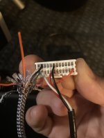
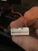
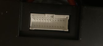
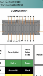
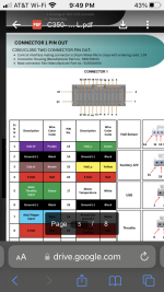
Should I view the “connector pin out” diagram from the non-wire side of the connector? Or the wire-side of the connector as I did and the image looks like the pins on the esc?


It’s a 3shul cl350. Hopefully I didn’t damage it but it’s saying the usb is faulty. At least there was no smoke and it’s not blinking red. The “ignition” wire (24 pin) was in and had positive 106v and was maybe going into where the usb should’ve. Ugh.
 

Attachments

  • AFF43896-D3AF-4960-9B48-2970C3C5AA96.jpeg
    AFF43896-D3AF-4960-9B48-2970C3C5AA96.jpeg
    1.6 MB · Views: 14
  • 2F9BA5E1-A315-4E5B-97E9-EE6986511468.jpeg
    2F9BA5E1-A315-4E5B-97E9-EE6986511468.jpeg
    1.5 MB · Views: 12
  • 629B3BA1-D406-4043-8426-C3E72B5F5E4A.jpeg
    629B3BA1-D406-4043-8426-C3E72B5F5E4A.jpeg
    889.2 KB · Views: 13
  • A7E469C3-F5F7-45F9-A02C-7D12A8365A6A.png
    A7E469C3-F5F7-45F9-A02C-7D12A8365A6A.png
    1.4 MB · Views: 14
  • 963BB2F4-0C55-438C-9CE7-EB2422EB2587.png
    963BB2F4-0C55-438C-9CE7-EB2422EB2587.png
    576.6 KB · Views: 17
  • D9B4DA5D-0B43-4ADF-AF1F-A97B97E505B9.png
    D9B4DA5D-0B43-4ADF-AF1F-A97B97E505B9.png
    1 MB · Views: 17
Last edited:
Hi, I would understand this such, that the controller integrated socket with male pins is shown in the controller documentation. Reason being, that the shown outline resembles what the socket looks like, not what the plug (with female contacts) looks like. Also, the controller pinout description references Molex connector p/n 559172410, which is the socket.

Molex datasheet

HTH, Thomas.
That's what I thought and how I added the wires. Phew. But for some unknown reason my computer states the usb is faulty when I plug it in. I added the wires by hand and maybe theyre not making contact with the pins and I can check that to be sure but assuming the three usb wires are making contact with the pins, which I think they likely are, do you have any advice? Or is there another way to run a test in vesc tool and set the motor up?
 
Well, USB is nothing else than 4 wires, two of which are +5V and Ground (0V), and two differential data lines, that should alternate between 5V and 0V. If you have a digital multimeter, you could at least probe that the supply and ground connections do their jobs. With an oscilloscope, you could also probe the data lines, if there is traffic going. For accessing the four wires, I have long ago made myself a small breakout setup from a USB extension cable (see attached pic).
 

Attachments

  • 20231010_215914.jpg
    20231010_215914.jpg
    2.7 MB · Views: 5
Well, USB is nothing else than 4 wires, two of which are +5V and Ground (0V), and two differential data lines, that should alternate between 5V and 0V. If you have a digital multimeter, you could at least probe that the supply and ground connections do their jobs. With an oscilloscope, you could also probe the data lines, if there is traffic going. For accessing the four wires, I have long ago made myself a small breakout setup from a USB extension cable (see attached pic).
The plug just uses three of the wires and skips the red. I don’t have an oscilloscope but would like to tell if the pins are actually making contact and I built the plug without the special crimp tool.

I plan to hook up the Bluetooth and can adjust parameters through that but don’t think I can run a motor test that way.

Maybe I could find someone else’s settings and enter them through Bluetooth
 

Attachments

  • 11D175D7-290D-43F6-9D1B-59BF48694C9A.png
    11D175D7-290D-43F6-9D1B-59BF48694C9A.png
    766.3 KB · Views: 4
Last edited:
I would not worry too much about not using the designated tool for those terminals. This normally has only long term consequences, when corrosion and vibration set in. Finding out if you have plain contact would also be doable with a DMM. Nowadays there are inexpensive ones out there that to the job and pay their money in no-time by lifting question marks for you right in an instant. For working with this controller, I can unfortunately not help you lacking experience... Hope someone else can chime in on that!
 
Got it going thanks to Hackey! I stupidly had the plus n minus wires swapped.

I have a multimeter but don’t know where to put the probes to see if the pins are making contact.
 
Back
Top