methods
1 GW
Here is thedatasheet for the LTC7000
If this makes your mind hurt, start with the LTC7001
(Same thing, less features, fewer pins)
We are going to go with the LTC7000
We are going to run (the equivalent of) 8pcs of IRFB4115
4 of those will be in parallel to control discharge
4 will be in parallel to control charge
This chip will allow us to run our uController (Arduino...) at 3.3V to conserve power (target of 10uA system total)
There are a lot of features... so lets look at them slowly.

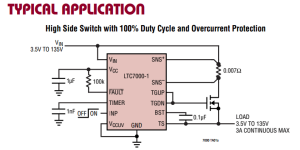
In this simplified diagram... (ignore most of the pins) we see that our (in this case) Battery attaches to the upper left corner to Vin, then drives through a shunt, through our Nchannel Power fet (or fets in our case) and out to the load. The circuit will work for just about any input... so it should span 4S to 28S without any issues.
Sizing the Shunt:
I would like to be able to rate the circuit at 125V 80A continuous for a nice clean 10KW (or 10hp after efficiency)
(No... you dont get the extra 250W... that goes to heat. Yes, there are 746KW to a HP.... but there are 254 really hot reasons why you only get 1HP out of 1KW)
So - 10HP sure sounds like a lot... but we are doing it with 125V so we only have to handle 80A
Heat goes up with the square of current while using a shunt... so calculations (and not eyeballing) is a requirement.
The LTC7000 expects to see 0V to 75mV... this is fairly standard.
The LTC then multiplies this voltage by a scaling factor of 20 and presents it to your uController in the form of 0V to 1.5V
We are using a Atmega328P with 10bit ADC's on 3.3V... so 2^10 = 1024 bits of resolution
A bit of resolution (depending on our Vrev.... lets assume 3.3V...) is 3.3V/1024 = 3.2mV
1.5V/3.2mV = ~466 steps out of our available 1024
80A equates to 75mV... so we are almost at a mV per amp (Maybe I should make them match <Dont fall into that trap - it all gets converted to bits anyway>
937.5uV equates to 1 amp through our circuit
18.75mV is what that will resolve as at the LTC output (1 amp)
So we get 5.86 steps per amp (pretty good!) or a resolution of 171mA across an 80A span
1% of 80A is 800mA
I would say we have sufficient resolution yes?
Now to the resistance value we use to achieve this.
I = 80A
V = 75mV
R must equal 937.5mOhms (again...) which cleans up nice to a 1mOhm shunt
Now... we got pretty specific there... but now we will back out, standardize values, calculate shunt power, and tune for triggers.
The math above was just to show us that with about a mOhm we would have WAY more resolution than we need.
We want our TRIP levels to be significantly higher than our running levels.
20mV is the default trip level
This can be set as high as 75mV
Since we want to actually use this current sensing input in our uController ... we are going to scale things such that the trip current is windowed while still allowing for resolution down low.
So far, pins we care about:
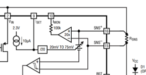
16 SNS +
15 SNS -
(this is where we read the actual shunt value)
10 iMon
(this is where we get the 20x output to our uController ADC)
Here we can see the pin used for setting trip levels

9 iSet
(If pin 9 is left open or over 2V then trip level defaults to 30mV)
You may be wondering what will happen when it trips?
well... in a minute we will attach a capacitor to the Timer input to set this delay time (and we will set it LONG). Then the circuit retries.
So - on point... lets calculate why it is that we dont want to use 1mOhm
P = I^2 * R
I = 80 A
R = 0.001 Ohms
So, P = 6.4Watts
Uh... Huston... we have a problem
SIX POINT FOUR WATTS
Now... I have been beating Ebikers over the head for YEARS trying to explain why power on the shunt must be respected and how power goes up with the square of current.
I swear nobody listens... but anyway...
So 6.4W will get that thing up to 65C and burn the crap out of your finger in no time. If you dont believe me... hook it up and try it. Even if you have a HUGE shunt - its still lame.
Yes - I understand this is the stock value in a CA... but the real average current there is 20A to 40A... so... 30A produces less than a watt... which is a BIG difference.
Got it (again )
)
So we want to dump less over the shunt
Best bet is to grab a part off the shelf and work around it.
An HONEST 100A is very different than a BURSTY 100A
This is the kind of bulk you are looking at: https://www.google.com/search?q=100...j7&sourceid=chrome&ie=UTF-8#q=100a+75mv+shunt
If... you want to produce 75mV
If we are willing to produce... say 30mV... and halve our resolution (which we are) then we can start getting somewhere.
1 amp of resolution is more than enough.
Call that 2 bits of resolution for quest... so 6.4mV... divide that by 20.... 320uA.... multiply by 100A as our trigger... and... we get 32mV
(pure luck - but not really)
So... we leave the iSet pin high, set threshold to 30mV, trip on 100A (for X milliseconds)
We get about half an amp of resolution... call it 1 amp
Thats well below the actual error of the system (which is ALWAYS 5% to 10%...) so good.
Now - 32mV/100A = 320uOhm shunt
Thats 3.2W peak
For 80A thats 2 watts (meh! still super high!)
Like I said... we should find a shunt and tune to it.
We can see... that something on the order of 100uOhms is more like where we will and and we will have somewhat poor current resolution... but enough to detect CHARGE, DISCHARGE, and IDLE yes?
Enough to terminate a charge current that is too high for our Crating Yes?
Give or take an amp... who cares...
Hook an 80A charger to a battery that can only charge at 20A... and you will see the point.
So - to be safe we overrate resistors in the power line by 10X
4X is getting close (think reflow... bad readings as they heat up... we want a LINEAR response)
For lack of time.... (and we could just double up components...) here is an off the cuff selection
300uOhms
10Watts
$2.60
http://www.mouser.com/ProductDetail...=sGAEpiMZZMtlleCFQhR/zWACB43HKDa1Flaoo0DE1j0=
You can no doubt do better... but thats what I am going with.
80A will produce 2 watts
Thats 5X margin
1 amp will produce 6mV at our uController ADC... and that is better than an amp of resolution.
100A will produce an excitation voltage of 30mV... and now we can leave that iSet pin open instead of trying to lay a resistor in there.
Now... to tune the hysteresis:
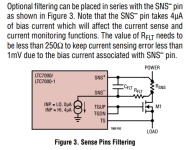
But first... it WOULD BE WISE to put a low pass filter on this shunt - as shown here:

Experience tells me to do it.. but I am going to let it fly and see what happens.
I will hack them one by one in the field if noise becomes an issue... or catch it on a redesign
If this were coming out of a board house... sure... populate them... or at least lay pads for the cap and a shorting pad for the resistor
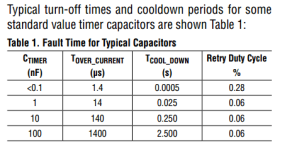
So - Fault Timer

Looks like 100nF (which is 0.1uF) will give us a nice long 1.4 MILLI second overshoot window
Eh... this would protect us from overshoot... but it would also false trigger constantly
So - re-evaluation
We want to detect short circuit levels of current
We want to stop our user from overheating the mosfets
We can protect the mosfets from overheating with temp probes... but for REAL HIGH currents they will pop before we can catch them.
We must not false trip...
And... now that RC filter on the shunt is starting to sound more important
So - hows about we bump the actual limit way up over 60mV... to 75mV... so something over 200A
Then... we can use the uController reading to blow open if the average current is exceeded.
Sigh... ya see... you cant have your cake and eat it too.
If we want to accurately measure current we should do so with an external hall sensor.
This resistor should be used only for detecting EXTREME over current like a short circuit
(we are learning here... things are not always as simple and clear as they seem)
So... what kind of noise currents should we expect with a circuit that is connected and precharged and in duty from 12V to 125V... at constant currents up to 80A with bursts to 200A or 300A?
No frigging idea.
Its most likely to trip on connect... but we will Precharge that...
All depends on the system.
Ok - so what kind of current clearly indicates that something is MEGA FUBAR and that we should KILL IT quick?
10X for sure... so 800A
Not really sure I want to find out what 800A looks like for 1.4mS... eh...
User wants to see 80A continuous with 200 - 300A bursts
Lets call 500A a short circuit and leave the time window long for now.
Stretching out our window to 75mV again...
Meh... I want cake and I want to eat it and I want high resolution cake...
@ 300uOhms we trip at 250A
ok... ok... so folks who want to run OVER 80 amps are just going to have to use this totally overbuilt mosfet section to run an External Gas Filled Contactor.
Over it.


We will call that 250A our burst trigger limit and set it to a super slow 1.4mS
We will be happy with our sub 1A resolution from 0A to 250A
We will tune FAULT C as needed in actual testing
Folks wishing to exceed 200A... even for a second or two... will be steered toward contactor drive
K... whats next?
Food. Been doing this for 12 hours.
-methods
If this makes your mind hurt, start with the LTC7001
(Same thing, less features, fewer pins)
We are going to go with the LTC7000
We are going to run (the equivalent of) 8pcs of IRFB4115
4 of those will be in parallel to control discharge
4 will be in parallel to control charge
This chip will allow us to run our uController (Arduino...) at 3.3V to conserve power (target of 10uA system total)
There are a lot of features... so lets look at them slowly.

In this simplified diagram... (ignore most of the pins) we see that our (in this case) Battery attaches to the upper left corner to Vin, then drives through a shunt, through our Nchannel Power fet (or fets in our case) and out to the load. The circuit will work for just about any input... so it should span 4S to 28S without any issues.
Sizing the Shunt:
I would like to be able to rate the circuit at 125V 80A continuous for a nice clean 10KW (or 10hp after efficiency)
(No... you dont get the extra 250W... that goes to heat. Yes, there are 746KW to a HP.... but there are 254 really hot reasons why you only get 1HP out of 1KW)
So - 10HP sure sounds like a lot... but we are doing it with 125V so we only have to handle 80A
Heat goes up with the square of current while using a shunt... so calculations (and not eyeballing) is a requirement.
The LTC7000 expects to see 0V to 75mV... this is fairly standard.
The LTC then multiplies this voltage by a scaling factor of 20 and presents it to your uController in the form of 0V to 1.5V
We are using a Atmega328P with 10bit ADC's on 3.3V... so 2^10 = 1024 bits of resolution
A bit of resolution (depending on our Vrev.... lets assume 3.3V...) is 3.3V/1024 = 3.2mV
1.5V/3.2mV = ~466 steps out of our available 1024
80A equates to 75mV... so we are almost at a mV per amp (Maybe I should make them match
937.5uV equates to 1 amp through our circuit
18.75mV is what that will resolve as at the LTC output (1 amp)
So we get 5.86 steps per amp (pretty good!) or a resolution of 171mA across an 80A span
1% of 80A is 800mA
I would say we have sufficient resolution yes?
Now to the resistance value we use to achieve this.
I = 80A
V = 75mV
R must equal 937.5mOhms (again...) which cleans up nice to a 1mOhm shunt
Now... we got pretty specific there... but now we will back out, standardize values, calculate shunt power, and tune for triggers.
The math above was just to show us that with about a mOhm we would have WAY more resolution than we need.
We want our TRIP levels to be significantly higher than our running levels.
20mV is the default trip level
This can be set as high as 75mV
Since we want to actually use this current sensing input in our uController ... we are going to scale things such that the trip current is windowed while still allowing for resolution down low.
So far, pins we care about:
16 SNS +
15 SNS -
(this is where we read the actual shunt value)
10 iMon
(this is where we get the 20x output to our uController ADC)
Here we can see the pin used for setting trip levels

9 iSet
(If pin 9 is left open or over 2V then trip level defaults to 30mV)
You may be wondering what will happen when it trips?
well... in a minute we will attach a capacitor to the Timer input to set this delay time (and we will set it LONG). Then the circuit retries.
So - on point... lets calculate why it is that we dont want to use 1mOhm
P = I^2 * R
I = 80 A
R = 0.001 Ohms
So, P = 6.4Watts
Uh... Huston... we have a problem
SIX POINT FOUR WATTS
Now... I have been beating Ebikers over the head for YEARS trying to explain why power on the shunt must be respected and how power goes up with the square of current.
I swear nobody listens... but anyway...
So 6.4W will get that thing up to 65C and burn the crap out of your finger in no time. If you dont believe me... hook it up and try it. Even if you have a HUGE shunt - its still lame.
Yes - I understand this is the stock value in a CA... but the real average current there is 20A to 40A... so... 30A produces less than a watt... which is a BIG difference.
Got it (again
So we want to dump less over the shunt
Best bet is to grab a part off the shelf and work around it.
An HONEST 100A is very different than a BURSTY 100A
This is the kind of bulk you are looking at: https://www.google.com/search?q=100...j7&sourceid=chrome&ie=UTF-8#q=100a+75mv+shunt
If... you want to produce 75mV
If we are willing to produce... say 30mV... and halve our resolution (which we are) then we can start getting somewhere.
1 amp of resolution is more than enough.
Call that 2 bits of resolution for quest... so 6.4mV... divide that by 20.... 320uA.... multiply by 100A as our trigger... and... we get 32mV
(pure luck - but not really)
So... we leave the iSet pin high, set threshold to 30mV, trip on 100A (for X milliseconds)
We get about half an amp of resolution... call it 1 amp
Thats well below the actual error of the system (which is ALWAYS 5% to 10%...) so good.
Now - 32mV/100A = 320uOhm shunt
Thats 3.2W peak
For 80A thats 2 watts (meh! still super high!)
Like I said... we should find a shunt and tune to it.
We can see... that something on the order of 100uOhms is more like where we will and and we will have somewhat poor current resolution... but enough to detect CHARGE, DISCHARGE, and IDLE yes?
Enough to terminate a charge current that is too high for our Crating Yes?
Give or take an amp... who cares...
Hook an 80A charger to a battery that can only charge at 20A... and you will see the point.
So - to be safe we overrate resistors in the power line by 10X
4X is getting close (think reflow... bad readings as they heat up... we want a LINEAR response)
For lack of time.... (and we could just double up components...) here is an off the cuff selection
300uOhms
10Watts
$2.60
http://www.mouser.com/ProductDetail...=sGAEpiMZZMtlleCFQhR/zWACB43HKDa1Flaoo0DE1j0=
You can no doubt do better... but thats what I am going with.
80A will produce 2 watts
Thats 5X margin
1 amp will produce 6mV at our uController ADC... and that is better than an amp of resolution.
100A will produce an excitation voltage of 30mV... and now we can leave that iSet pin open instead of trying to lay a resistor in there.
Now... to tune the hysteresis:
But first... it WOULD BE WISE to put a low pass filter on this shunt - as shown here:

Experience tells me to do it.. but I am going to let it fly and see what happens.
I will hack them one by one in the field if noise becomes an issue... or catch it on a redesign
If this were coming out of a board house... sure... populate them... or at least lay pads for the cap and a shorting pad for the resistor
So - Fault Timer

Looks like 100nF (which is 0.1uF) will give us a nice long 1.4 MILLI second overshoot window
Eh... this would protect us from overshoot... but it would also false trigger constantly
So - re-evaluation
We want to detect short circuit levels of current
We want to stop our user from overheating the mosfets
We can protect the mosfets from overheating with temp probes... but for REAL HIGH currents they will pop before we can catch them.
We must not false trip...
And... now that RC filter on the shunt is starting to sound more important
So - hows about we bump the actual limit way up over 60mV... to 75mV... so something over 200A
Then... we can use the uController reading to blow open if the average current is exceeded.
Sigh... ya see... you cant have your cake and eat it too.
If we want to accurately measure current we should do so with an external hall sensor.
This resistor should be used only for detecting EXTREME over current like a short circuit
(we are learning here... things are not always as simple and clear as they seem)
So... what kind of noise currents should we expect with a circuit that is connected and precharged and in duty from 12V to 125V... at constant currents up to 80A with bursts to 200A or 300A?
No frigging idea.
Its most likely to trip on connect... but we will Precharge that...
All depends on the system.
Ok - so what kind of current clearly indicates that something is MEGA FUBAR and that we should KILL IT quick?
10X for sure... so 800A
Not really sure I want to find out what 800A looks like for 1.4mS... eh...
User wants to see 80A continuous with 200 - 300A bursts
Lets call 500A a short circuit and leave the time window long for now.
Stretching out our window to 75mV again...
Meh... I want cake and I want to eat it and I want high resolution cake...
@ 300uOhms we trip at 250A
ok... ok... so folks who want to run OVER 80 amps are just going to have to use this totally overbuilt mosfet section to run an External Gas Filled Contactor.
Over it.
We will call that 250A our burst trigger limit and set it to a super slow 1.4mS
We will be happy with our sub 1A resolution from 0A to 250A
We will tune FAULT C as needed in actual testing
Folks wishing to exceed 200A... even for a second or two... will be steered toward contactor drive
K... whats next?
Food. Been doing this for 12 hours.
-methods

