Molicel 20s 8p build questions?

Jonboy

1 kW
Joined
Aug 18, 2013
Messages
318
Location
S. Wales
Hi Guys, I'm building a molicel 21700 pack 20s8p.. I'm struggling with calculating nickel strip sizes.. I've done some homework!!
But still not happy to proceed with the build..

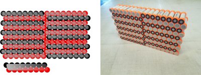
What i'm thinking is pieces of 8-10 mm x .2mm strip made up in the arrangement attached or maybe down to .15 for the parrallel links. alternatively a single .2 patch as in the pic. my goals are over 150 battery amps, it would be good to make it 250 amp tolerant as I have the big Nuc controller that I will put on the raptor at some point.

I realise i will have to beef up the bus bar connecting both sections of the battery and the termination ends of of the series +- ... Many thanks in advance

Cheers

Jon
 

Attachments

  • Graphic1.jpg
    Graphic1.jpg
    1.4 MB · Views: 369
I don't get your layout.. where are the 20s connections? Seems to be two 10s8p arrays that will be joined somehow?

The parallel connections are less important since normally only small current will flow there. Series connections carry the current but actually is less critical than one might think in this type of layout since the paths are very short. Compared to the resistance in the batteries they don't add much but make them as large as you have equipment to do.

Pitfalls are unbalanced connections at the plus and minus of the pack (and any deviation from the straight path between cells) since they will load the cell strings differently. Make sure the paths and cross sections from each series string to the wire connection point is equal.
 
Jonboy said:
I'm building a molicel 21700 pack 20s8p..
<snip>
my goals are over 150 battery amps, it would be good to make it 250 amp tolerant
Some food for thought, in case you haven't looked into this part:

250A / 8p = 31.25A per cell.

Some testing of the cells you're probably referring to:
https://lygte-info.dk/review/batteries2012/Molicel%20INR21700-P42A%204200mAh%20(Gray)%20UK.html
shows
at that rate, then even when fully charged the cells will sag to their nominal *average* voltage (3.6v), which is a huge loss of power (watts) for your system. 4.2 - 3.6v = 0.6v per cell, x 20s = 12v of battery pack sag under that load! 250A * 12v = 3000watts of lost power that doesn't make it to your wheel, and all that lost power is heating the cells themselves internally). (this doesnt' account for any sag losses in the pack construction and connectors, it's *only* the internal cell losses) By the time you've used only 3Ah of each cell (24Ah of the 8p pack), they're sagging down closer to 3.2v, and you won't get much more than another half Ah of capacity out of each cell at that rate.... (assuming frequent use at that rate vs just bursts)


150A / 8p = 18.75A per cell.

The same page shows the cells would probably sag to around 3.8v or less at this rate. So less sag, but still significant; you can calculate the power losses based on the above.
 
I think if Jonboys goal is to have 150amp of PEAK power that lasts just 1 or 2 seconds when mashing the throttle then the sag projected above should be tolerable? When his peak amps settle on his cro-motor he'll probably be using more like 50 or 60 amps.

On full initial throttle the pack will sag to 76v.


To answer your question, you will need some thick nickel plated copper wire going right across the cells from one side of the pack to the other ro connect the left hand and right hand stacks. If you can weld the .2 nickel and maybe weld .15 matching strips over the top to ensure nickel matches current flow of each cell.
 
Back
Top