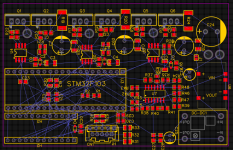
Motor Controller with Customizable Electronics, easy DIY and repair OpenSource

casainho

10 GW
Joined
Feb 14, 2011
Messages
6,047
Project page: https://github.com/EBiCS/EV_Motor_Controller_Customizable_Electronics

The target for this EV motor controller is to power small EVs like EBikes or EScooters like Xiaomi M365.

Main objectives:
- Possible to add custom electronics: for reusing this motor controller on different devices, customize it for the specifics of each project.

- Easy to build and repair: build at home DIY. Use popular components. Repair if needed or unsolder the components to reuse on another projects.

Characteristics:
- Header for custom electronics board: other board can be connected, like a perforated board with some simple electronics for instance to add CAN communications, 2x UARTS: full duplex or half duplex; specific circuit for EBikes torque sensors; SPI or I2C for cheap popular OLED displays; add a Bluetooth module; add NRF52 board with EBike ANT+ LEV wireless standard, etc.

- Easy to build and repair as DIY: no fine pitch components as like a STM32 microcontroller - uses DC-DC modules as also the Bluepill STM32 board. The resistors and capacitors are 0805. The ICs are SOIC8 and SOIC14. This means it can be easily soldered at home.

- Popular components: Uses the popular Bluepill STM32F103 board, meaning it is easy to develop firmware for it. Uses popular components common found on EBikes chinese motor controllers.

Current state

As of 31.12.2021,
- the schematic was discussed between Andrii and Casainho. Andrii already did a similar motor controller and is confident on this schematic.
- the PCB was designed by Andrii
- the PCB was ordered and next steps are to build and test the motor controller, using this OpenSource firmware: https://github.com/Koxx3/SmartESC_STM32_v3

Schematic:


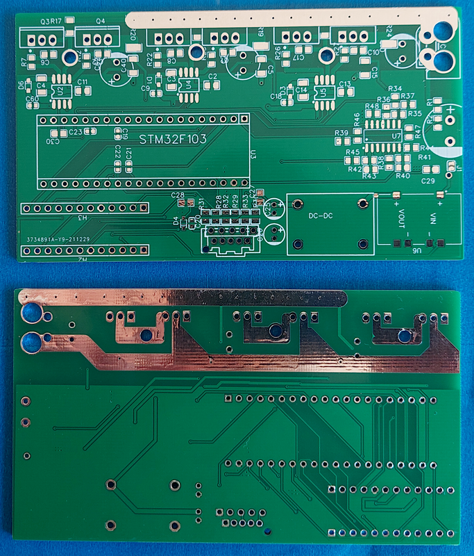
PCB:
pcb_3d.png
 
Glad to see this!

I have been toying with a similar idea - board with MOSFET, gate drivers, DC-DC plus miscellaneous to which bluepill can be plugged.

Cost is perplexing, STM32F103C8T6 (or rather CBT6?) processor alone (even w/ 100+ units) is costlier than the bluepill w/ that processor.

Though it seems ST is not aggressively pushing STM32F1xx's for motor control (MCSDK 5.Y versions have stopped supporting it, only legacy MCSDK retains it), it is ubiquitous on Chinese ebike controllers, Votol's (https://endless-sphere.com/forums/viewtopic.php?p=1693774#p1693663) too have the same processor. As an aside, it seems ST Link internally uses the same processor.
 
casainho said:
Project page: https://github.com/OpenSourceEBike/EV_Motor_Controller_Customizable_Electronics

The target for this EV motor controller is to power small EVs like EBikes or EScooters like Xiaomi M365.

Very interesting project but I get an error for the github link.
 
SlowCo said:
casainho said:
Project page: https://github.com/OpenSourceEBike/EV_Motor_Controller_Customizable_Electronics

The target for this EV motor controller is to power small EVs like EBikes or EScooters like Xiaomi M365.

Very interesting project but I get an error for the github link.
I moved the project to another place on GitHub, here the link: https://github.com/EBiCS/EV_Motor_Controller_Customizable_Electronics
 
THIS! WOW!

So I have been toying with more or less the same ideea. There are a lot of two-board designs out there, why not just take one that already exists with the microcontroller and just make the power electronics board around it? Half the work is done already with something like the arduino nano BLE. (microcontroller, usb connection, the 3.3v supply, even bluetooth)
So i searched for arduino based controlles and found ... mostly nothing.

But THIS is even better! Project by people with actual experience in the field, around a uC actually used for controllers!
DIY friendly form the start! Not to speak about the software also in development!
I didn't even know that the bluepill existed!

Thanks oh thanks for this!

I have some questions:

1) why bluepill and not blackpill? blackpill seems the nicer option at first glance, and the price difference is small (imho)
2) the microcontroller seems a bit slower than say that used for the VESC - what max ERPM do you expect it to be able to reliably sustain in FOC ?
3) what power do you expect the board to be used for?

Thanks!
And thanks again for this wonderful project!
 
badgineer said:
1) why bluepill and not blackpill? blackpill seems the nicer option at first glance, and the price difference is small (imho)

A: Because the firmware EBICS is only developed for the same microcontroller of BluePill. It will not work on the blackpill.

badgineer said:
2) the microcontroller seems a bit slower than say that used for the VESC - what max ERPM do you expect it to be able to reliably sustain in FOC?

A: I don´t know but I know this microcontroller is used on EBikes, hoverboards, electric unicycles and electric scooters, so should work for all this applications.

badgineer said:
3) what power do you expect the board to be used for?
I already asked that question to the hardware / board developer and I think it will be 1kW max. Anyway, on the escooter Xiaomi M365, there are people modding the controller to get 2 times more at least.
 
The boards arrived. I am still to receive the components, maybe this week. I wish to make another board version that is size optimized, I want it to be smaller. I need to evaluate if 0603 components are ok to solder, because the 0805 seems to take some good space.

If anyone want to try improve the board, here are the current source files: https://github.com/EBiCS/EV_Motor_Controller_Customizable_Electronics

I am busy on the firmware side, so I will take some time to solder the components and test.

 
There are a lot of things that should be improved on next board version, like the footprint for the X60 battery conenctor or
the 12V -> 5V DC-DC footprint.

I could not find some ICs from Mouser and I had to buy them from Aliexpress. I already solder them on the board and I am now waiting to receive the capacitors and resistor from Mouser as also the 80V -> 12V DC-DC.

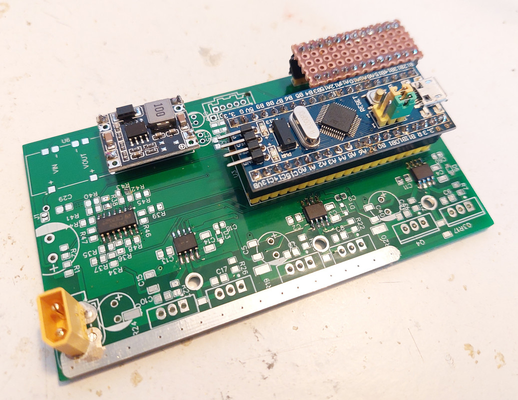
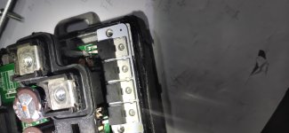
Here pictures of current state. Nothing was hard to solder until now, and the worst part is already done, that SOC ICs.

That small perforated board is the board for the custom electronics. To test this motor controller, I will need to use a throttle and a brake, so I will need to solder 2 resistors on that custom electronics board to adapt the throttle signal to the Bluepill analog input signal. I will need to probably do the same for the brake signal. Although the perforated board is very small, it is more than enough to do this:


this PCB is good for prototype testing purpose, looking forward to seeing the result. if everything is ok, definitely can polish the PCB size, say for example to fit for some very cheap trapezoid controller box. 0603 is a better choice, 78M/L05 could be a alternative replacement of mini360.
 
flute2k3@hotmail.com said:
this PCB is good for prototype testing purpose, looking forward to seeing the result. if everything is ok, definitely can polish the PCB size, say for example to fit for some very cheap trapezoid controller box. 0603 is a better choice, 78M/L05 could be a alternative replacement of mini360.
What would be the disadvantages of going with 0603 compared to currently 0805?

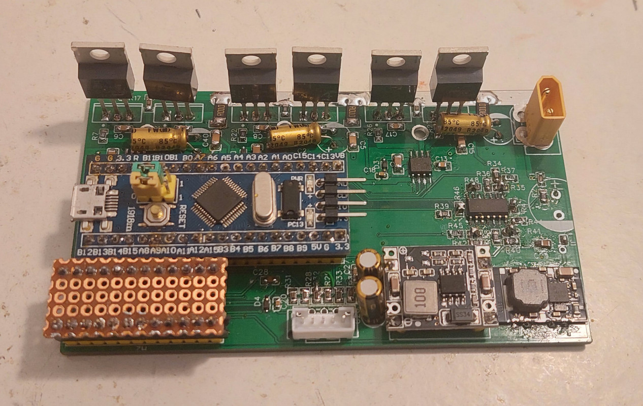
It is almost finished the soldering of components:
 
casainho said:
flute2k3@hotmail.com said:
this PCB is good for prototype testing purpose, looking forward to seeing the result. if everything is ok, definitely can polish the PCB size, say for example to fit for some very cheap trapezoid controller box. 0603 is a better choice, 78M/L05 could be a alternative replacement of mini360.
What would be the disadvantages of going with 0603 compared to currently 0805?

It is almost finished the soldering of components:

IMHO, I do not see any disadvantage, compared with 0402, 0603 is easy to solder same as 0805, and it is cheaper than 0805. most of the case the application is far below its max power rating.

Good to know you are almost done, if you could poste some video on youtube will be perfect! I can't wait to see your testing report :shock:
 
flute2k3@hotmail.com said:
casainho said:
flute2k3@hotmail.com said:
this PCB is good for prototype testing purpose, looking forward to seeing the result. if everything is ok, definitely can polish the PCB size, say for example to fit for some very cheap trapezoid controller box. 0603 is a better choice, 78M/L05 could be a alternative replacement of mini360.
What would be the disadvantages of going with 0603 compared to currently 0805?

It is almost finished the soldering of components:

IMHO, I do not see any disadvantage, compared with 0402, 0603 is easy to solder same as 0805, and it is cheaper than 0805. most of the case the application is far below its max power rating.

Good to know you are almost done, if you could poste some video on youtube will be perfect! I can't wait to see your testing report :shock:
In fact there are some components in 0603 on the board, it was more a mistake. It is clear that 0805 are easier to solder, but 0603 can also be soldered ok. I wounder if 0603 is ok for DIY.

And if was you, to make the board small, would you place components on the bottom layer? I verified that due to TH components, the bottom layer board has some width, maybe similar to have SMT components there.
 
casainho said:
flute2k3@hotmail.com said:
casainho said:
flute2k3@hotmail.com said:
this PCB is good for prototype testing purpose, looking forward to seeing the result. if everything is ok, definitely can polish the PCB size, say for example to fit for some very cheap trapezoid controller box. 0603 is a better choice, 78M/L05 could be a alternative replacement of mini360.
What would be the disadvantages of going with 0603 compared to currently 0805?

It is almost finished the soldering of components:

IMHO, I do not see any disadvantage, compared with 0402, 0603 is easy to solder same as 0805, and it is cheaper than 0805. most of the case the application is far below its max power rating.

Good to know you are almost done, if you could poste some video on youtube will be perfect! I can't wait to see your testing report :shock:
In fact there are some components in 0603 on the board, it was more a mistake. It is clear that 0805 are easier to solder, but 0603 can also be soldered ok. I wounder if 0603 is ok for DIY.

And if was you, to make the board small, would you place components on the bottom layer? I verified that due to TH components, the bottom layer board has some width, maybe similar to have SMT components there.

I did few due to space limit, but only for resistor and capacitor (0603 size), it is not recommended to place on bottom layer for mess production, but for DIY I would say it is ok for resistors and capacitors in SMT form.
 
Do you have experience designing motor controllers? and if so, which currents and mosfets number?
 
casainho said:
Do you have experience designing motor controllers? and if so, which currents and mosfets number?

never, this is why I'm so interested in your work.

I do play and dissemble a lot of controllers, including votol em-30s em-50s, IMHO votol series is a great product if well tamed, can fit almost every application from escooter to ebike, the programmable regenerative braking is awesome... there are only two cons: closesource firmware and size too big. I was trying to find some opensource boards or mods that can work on some small size stm32f103 based controller but failed until your post.

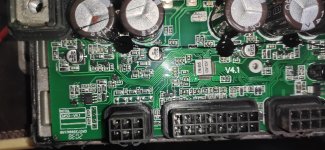
not sure if it is helpful for you, the votol series use smt32f103, MagnaChip MDP1991 120A100V, specifically for em-50s, it uses 2 in parallel per arm (12 in total) to support up to 96V/55A capability. it applies to mosfet Rds_ON resistor current sensing so none of current existing opensource F103 based firmware can work on it.
IMG_20210816_204824.jpg
IMG_20210816_204038.jpg
 
The developer that designed that board is busy, and is trying to design one with 18 mosfets (has some issues).

So we need help to design this 6 fets board, the next version, maybe with the 0603 components and make it small as possible, but still DIY friendly as possible, with the Bluepill and the custom electronics header.
 
Hi.

Just some questions (btw, I won't be able to design/improve the board myself as much as I'd like to, no experience in designing smt/smd boards, so feel free to ignore me with my silly questions)
Why do you think going to smaller smd components is the way to go? Taking a look at the board, the smds seem to use up only a small percentage of the space. There still is plenty of "free" space on the board to pack it tighter, and you also have much bigger devices on it! Maybe replacing the separate power supplies with on-board components would free up more space. Maybe loose the power connector (if it's OK to solder the phase wires to the board, why not also the battery cables?)

Br,
 
badgineer said:
Hi.

Just some questions (btw, I won't be able to design/improve the board myself as much as I'd like to, no experience in designing smt/smd boards, so feel free to ignore me with my silly questions)
Why do you think going to smaller smd components is the way to go? Taking a look at the board, the smds seem to use up only a small percentage of the space. There still is plenty of "free" space on the board to pack it tighter, and you also have much bigger devices on it! Maybe replacing the separate power supplies with on-board components would free up more space. Maybe loose the power connector (if it's OK to solder the phase wires to the board, why not also the battery cables?)

Br,
Everyone on the telegram group for developers, are suggesting 0603...

Yes, that power connector, and maybe reduce the space between the mosfets, etc.
 
Hi.

casainho said:
If anyone want to try improve the board, here are the current source files: https://github.com/EBiCS/EV_Motor_Contr ... lectronics

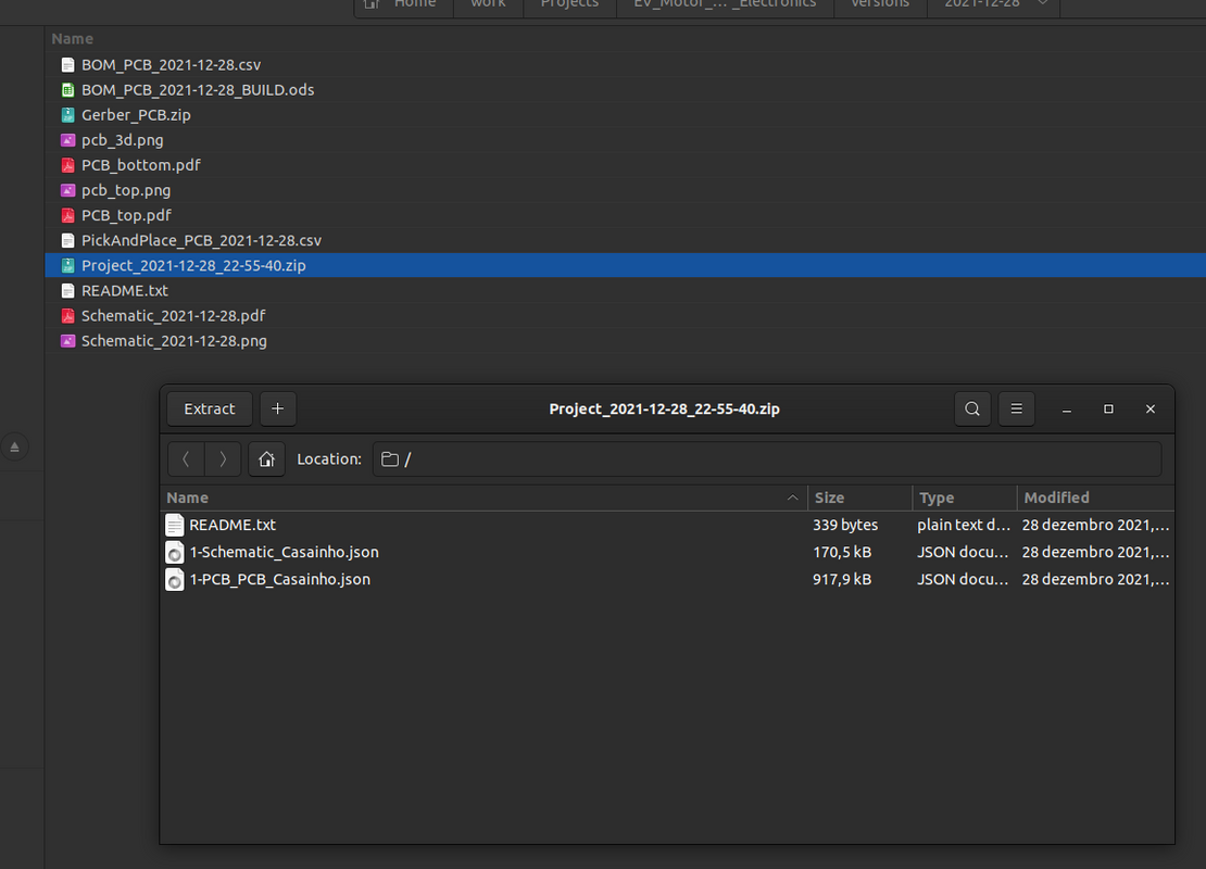
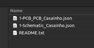
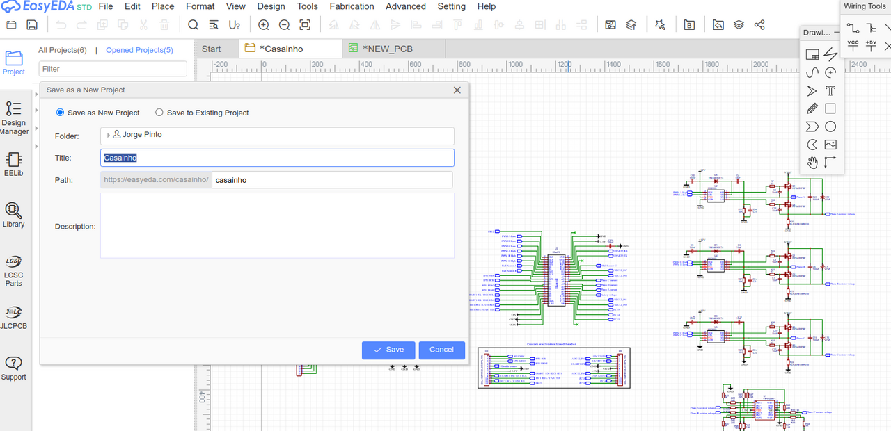
I could not open the Project_2021-12-28_22-55-40.zip with the windows .zip archive manager, and also not with 7z. I also did not succeed importing it into online easyeda, that's the software the project was made in, right?

Am I doing something wrong here?

Thanks!

Br,
 
badgineer said:
I could not open the Project_2021-12-28_22-55-40.zip with the windows .zip archive manager, and also not with 7z. I also did not succeed importing it into online easyeda, that's the software the project was made in, right?

Am I doing something wrong here?
I just tested and all works for me. I verified that I need to import to EasyEda the ZIP file:


Worked this time. Thanks!
I got a corrupted download before ... twice. Either that or I did something stupid twice.... :oops:
Br,
 
Hi.

Me again with my silly questions.

By the way, if at any time I become annoying and you've had enough of my un-helpfulness, please let me know (post or PM), and I will stop posting in this thread. I know I'm not particularly helpful but I am both curious and maybe hopefully just a little bit helpful, even if only as a "rubber duck"

Regarding the schematic:
  • What is the purpose of the C62 and C40 ? I assumed it's to filter out noise / compensate impedance. But in this case the 2 capacitors are between VBAT and Phase_A_resistor_voltage, not VBAT and GND, as I would have expected, in which case the noise is just shorted to the current sense signal - before amplification through the LMV324IDT! Isn't this bad?

  • The 10mOhm current sensing resistors/shunts are 3W rated. This is reached at 17.3Amps approximately if I'm not mistaken. It gets only 1/2 the phase current, so 3W are reached at 34.6 phase Amps. (so higher phase amps than this risks overheating the current sense shunts). Isn't this limit a bit on the low side? A good TO220 is capable of 100A. (later edit: just saw that the chosen FET - IRF540NPbF actually can only do 33A, and has 44mOhm RDSon, so the shunts are OK I guess. I was thinking more of a <5mOhm RDSon FET like IPP023N10N5, in which case the shunt would have had bigger power dissipation than the FETs. )

Regarding the PCB design:
  • There are some long thin traces in parallel with - and very close to - the VBAT thick trace. For example the phase resistor voltage going to the opamp. I'm thinking about the large current through the VBAT trace inducing noise in the signal - which is bad imho... isn't it?

PS: I am not really implying bad design here, I think it's more likely I don't understand, than these to be real sub-optimal choices, and I'd like to understand why these things are designed this way. Also, maybe 1 in 10 questions ends up highlighting an error - having an idiot poking around and asking questions is sometimes helpful :)

Oh, and what is J1 for?
And why that particular FET? Why 100V FET when the 12V power supply has a max of 72V? Also, 44mOhm RDSon seems high to me.
I searched 10 min and found that you can have much better FETs >= 75V at very good price. For example IRFB3607PBF is even cheaper on mouser while having a 6x smaller RDSon.

Br,
 
I actually don't understand why not use 78M/L05 for 12 to 5v DC/DC converter. it will greatly reduce the size. consider an average operation current consumption of 100mA at 5V inputs, it draws only 0.7w on this regulator, compared with a 200+ W level motor it is nothing. on the other hand, even if you use high eff switching DC/DC converter, the quiescent current of AMS1117 alone is 5mA, make it impossible for long time standby, you anyway have to set a switch/breaker from power input.
 
Hi.

I did a first try of placing the parts on the board - managed to fit them on a 95x60 board (initial one was 105x60)
But I removed the power connectors and replaced them with 2 pads. I might be able to squeeze them in again though if they are desired.

Oh and I changed all 0603 to 0805 :D.
So a smaller form factor is achievable even with 0805. How small should it be? :)

I started from schematic, "stole" some features of the initial design, but I did quite some changes too.

6fet_bluepill_initialplace.png

I am really curious about this though:
"What is the purpose of the C62 and C40 ? I assumed it's to filter out noise / compensate impedance. But in this case the 2 capacitors are between VBAT and Phase_A_resistor_voltage, not VBAT and GND, as I would have expected, in which case the noise is just shorted to the current sense signal - before amplification through the LMV324IDT! Isn't this bad?"

Br,
 
Back
Top