Need help with busbar calculations

BenjAZ

100 mW
Joined
Sep 4, 2017
Messages
49
Hi,

I usually build 10s, 13s and 20s battery pack for ebikes, but I've been asked to build a 26s36p battery pack for a home made electric motorcycle.
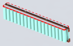
Instead of building one block battery (47kg), I'd rather make it modular, with 26 "bricks" of 36 cells in parallel (1.8Kg each). This way, the battery will be a lot easier to move around and assemble in the motorbike.
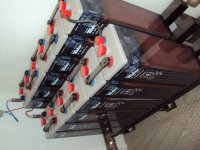
Each brick will have + pos and - neg terminals, and then connect all the bricks in series with wires. The same way they do with the 2V batteries for solar panels. (Photo attached to show the serial connections).

The battery will have a demand of 150A continuous current and unto 600A peak.

I'm used to calculate nickel strip width and thickness to deal with the current demand, but for this brick design and the current demand I want to spot weld all the cells to a copper? strip (27-30mm wide) and a copper? busbar as a spine going from the bottom to the top to carry all the current.

I wonder if you could shed some light with tables, formulas or links to help me with the calculations of best section, material,... for the busbar and strip.

What's the best way to ensure the right contact between the busbar and stip? Bolted would be enough?

Thanks
 

Attachments

  • Captura de pantalla 2019-03-04 a las 12.53.48.png
    Captura de pantalla 2019-03-04 a las 12.53.48.png
    18.8 KB · Views: 1,082
  • DSC04031.JPG
    DSC04031.JPG
    75.5 KB · Views: 1,081
That's a good option.

I'm considering cell level fuse soldered or spot welded to the busbar
 
This would be the render of my idea of this modular battery.

I know, it doesn't have any insulation or protection. It's just to make all the bricks visible.
And still doesn't have the serial connexions
 

Attachments

  • Render 26s36p.JPG
    Render 26s36p.JPG
    27 KB · Views: 1,046
best way to calaculate is to take the current and hold to 12mm2 per 100A DC with pure copper.

that holds to the norm used in the industry and ensures you dont burn up the pack.
 
You can use nickel strips for the series connections and only use the bus bars at the ends. Saves a lot of work.

I agree you may have a heating issue with the middle layer. It would be hard to make that work well without using some kind of active cooling. Simplest approach would be to have a small (1/4") space between the layers and use a small blower to blow air through.

 
I've been experimenting with 6mm polycarbonate insulation sheets (i.e. greenhouse glazing) as thermal spacers between battery layers. Being exposed, I could indeed blow air in-between (but I won't, at least not initially). To wit:

View attachment 1

Battery cross section4.1200.jpg

YMMV.
Michael
 
if you are loading down cells so much that you need active cooling might mean you need a bigger battery.
 
I found a table where it says it needs a section of 200mm2 of copper to deal with 600A. So this would make the busbar 4mmx50mm.

This is the 1s36p with the massive busbars on both sides (hiding the heat shrink). I'd use 20A fuse wire from each cell to the busbar (not drawn):
Render v0.2 1s36p.JPG


This is the 26s36p battery pack with the copper links between blocks:
Render v0.2 26s36p.JPG

Weight estimation: 43kg in cells, 36kg in copper, 1kg in plastic (cell holders and heat shrinks),...
Not sure if they are willing to pay for the 36kg of laser cut copper parts it would have :lol:

Thanks for all your suggestions, I'm going to redesign the battery to reduce copper
 
flippy said:
best way to calaculate is to take the current and hold to 12mm2 per 100A DC with pure copper.

that holds to the norm used in the industry and ensures you dont burn up the pack.

12mm2 per 100A DC, means 72mm2 for 600A, isn't it?

This would reduce massively the use of copper from 36kg (based on wrong info I found) to 13.5kg. mmmm I like it :D
 
fechter said:
You can use nickel strips for the series connections and only use the bus bars at the ends. Saves a lot of work.

I agree you may have a heating issue with the middle layer. It would be hard to make that work well without using some kind of active cooling. Simplest approach would be to have a small (1/4") space between the layers and use a small blower to blow air through.

Img_1098.jpg

The idea of making it modular is the ease of repair. If one cell fails, it's easier to access and replace. Or even, having one spare module and replace it while repairing the faulty one.
However, this would be a more expensive option.

Anyway that's a good way to reduce cost and weight. I'll consider your suggestion. Thanks
 
MJSfoto1956 said:
I've been experimenting with 6mm polycarbonate insulation sheets (i.e. greenhouse glass) as thermal spacers between battery layers. Being exposed, I could indeed blow air in-between. To wit:

IMG_6874.1280b.jpg

Battery cross section4.1200.jpg

YMMV.
Michael

What software have you used to draw that battery?
 
BenjAZ said:
flippy said:
best way to calaculate is to take the current and hold to 12mm2 per 100A DC with pure copper.

that holds to the norm used in the industry and ensures you dont burn up the pack.

12mm2 per 100A DC, means 72mm2 for 600A, isn't it?

This would reduce massively the use of copper from 36kg (based on wrong info I found) to 13.5kg. mmmm I like it :D

calculations is made on very short distances and using pure copper, so make sure it does not have any brass or other assorted crap in it.
 
Back
Top