Problems with battery

Mike_Kelly

10 mW
Joined
Apr 25, 2023
Messages
29
Location
North America
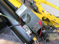
I have a 36v 720wh battery that has been waiting to be installed for 8 months. So it reads 15v. I just noticed they sent me the wrong charger with it, so I can't charge it. I built a wiring hardness that allows for it and a external bottle battery with ideal diode for isolation. When I test the harness with a lab power supply. It works correctly. But when I hook it up the battery I get .7 volts out. When I measure at the input to the diode it is 1v. Something weird is going on with the fet in the diode or something with the BMS. Any thoughts would be helpful. Thanks in advance.
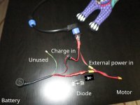
Wiringharness.JPG

IMG_1246.JPG
 
I'd check the voltage at the pack level. If it's 15v at the pack level, it's very likely dead.
 
If the Battery has a BMS, it would have turned off the output when the internal cells got too low, I would think that 17V is just leakage around the switching transistors. I would set my lab supply to 1A constant current and 36 volts. Use that as a charge,

The operating voltage of your 36V battery depends on whether it is Li-ion or LiFePO4. Li-ion charges at 42V and I forgot what';s used for LiFe, so I believe 36V is a good value for testing,
 
I am seeing a board for a diode but I am not seeing a diode on the board. That is confusing me.
 
@docw009 I hope you are right. It is a Lion but my lab PS only goes to 30v so I am getting a 42v charger.
e-beach it is an ideal diode. Flatpack. On the other side of the board.
 
Can you access your BMS wiring so you can test each cell group?
 
Wrong charger? 36V Lithium battery pack? capacity 20Ah?
The charing current should be 4A to 10A.
Suggesting you the henryuan 42V 5A lithium battery charger, supports customization.
 
There is something else I am not understanding. Is your charging wires looping to the main battery while you have a second battery attached or do you disconnected the charging wires before you use the second battery?

Also, checking the diode is easy. Simply apply a voltage from your bench charger to one side of the diode and measure what comes out of the other side. Is this what you did?

BTW. if your cells are like 1.5v each, that battery is almost assuredly dead.
 
The battery has separate output and charge lines. The diode works when not connected to the battery. My theory is that there is a bms that has locked the battery down, There is voltage but no current to activate the switch so no output voltage.
 
......... My theory is that there is a bms that has locked the battery down, There is voltage but no current to activate the switch so no output voltage.
I really don't understand what you are saying here.

A: Why would the BMS "lock" the battery down?

B: What switch are you referring to that is not being activated?

Please elaborate.
 
The battery has a BMS that will not allow output when the voltage drops too low. The switch is the ideal diode that has a fet switch to cut-out output when the diode inside is reverse biased.
 
This is kind of ghetto, but if your bench supply has floating outputs, you could put it in series with your (working) bottle battery and try to charge the pack that way.
 
Please let me know if I have this wrong, but your Low Voltage Cutoff function is not allowing you to get a proper voltage reading on your pack?
 
I believe you are probably correct, One of his 10 groups is under 3V, The problem is if it gets too far below 3V, the BMS will never let it recharge.
At 15v it would seem to me that more then one of the 10 groups is under 3v. The only way to know is for the OP to cut it open to access the bms wiring but has already stated that is not in the plans.

Ok, I guess I haven't been paying attention. So for how long have those cheep Chinese BMS' not allowed for a charge after a LVC event?
 
........ I just noticed they sent me the wrong charger with it, so I can't charge it. .......

So what kind of charger did they send you in the first place?
 
At 15v it would seem to me that more then one of the 10 groups is under 3v. The only way to know is for the OP to cut it open to access the bms wiring but has already stated that is not in the plans.

Ok, I guess I haven't been paying attention. So for how long have those cheep Chinese BMS' not allowed for a charge after a LVC event?
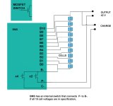
The Li-ion models typically spec a minimum group voltage of 2.75V. Below that, it won't allow recharge, It's conservative, as most cell makers allow you to go down to 2.5V.

When a group is out of spec, the BMS isolates the cells from ground. When you're reading 17V, you're really looking at leakge across the BMS switch transistors.


BMS_mosfets.jpg
 
The Li-ion models typically spec a minimum group voltage of 2.75V. Below that, it won't allow recharge, It's conservative, as most cell makers allow you to go down to 2.5V.

When a group is out of spec, the BMS isolates the cells from ground. When you're reading 17V, you're really looking at leakge across the BMS switch transistors.


View attachment 353310
Sounds like sophistication of a cheap Chinese BMS from an unknown Chinese company that has zero concern of liability. On the other hand I haven't been paying attention to these kinds of things lately. But it still points to the OP having to open the battery pack because even a 42v Li-on charger won't fix the problem you have kindly described for us. And if he nicks a battery in the process, then it can be replaced with the other dead cells.
 
Back
Top