Reparing R4850G2 that had logic side grounded

BitBricks

10 µW
Joined
Mar 11, 2024
Messages
6
Location
Texas
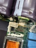
Been working on a project and unfortunatly last night, all my faulty here, ran into a big snag. On my 4850g2 unit, I have ESP32 inside of it to act like a wireless controlled system that worked amazing for about a week or so. The ESP32 was powered using 12v from fan header (my board has buck of course), and like I said everything ran perfect for a week. Last night, I bricked the firmware on esp and had to pull it all apart. Flashed it, assmebled and went to plug it in but a big single spark flew out and that was it. No tripped breaker or anything and no smell. Inspected the entire unit and could not find Anything that looked burnt or blew. What I discovered is that the 12v source wire (coming form 12v pin on the fan header) got jammed between lid and the body and shorted! Very much my careless fault here, was late nigth after work and exhausted.

So now, I hear the unit emit the usual/normal electrical "noise" when 240v is applied. But output nor the fan turns on as entire logic side is down. No lights on the logic board and no 12v to the fan. Seems like maybe a resistor or something between the AC source to the Logic has been damaged, but no idea on how to find it. Somone in first few posts on here had similar issue due to CAN isolation issue and 12v, however their MOSFETs on the side of the unit blew and such. My unit has zero damage that I can find, so I wonder if may someone could help. Ordered a new 4875 unit from china but it wont be here for weeks and batteries are alreadly low and would love to not leave them depleted for long time.

Thanks in advance!
 
You broke a passive component, not hard to do even with static electricity where you rub your feet on the shag carpet and you touch the light switch and you feel the zap, but when you hear or see something then thats like a million static electricity discharges all at once. No passive component can undertake that kind of abuse. Remember that if no components are damaged, the pcb board itself could be damaged with zero clues, could be there was a start in delamination of a pcb board and the spark occured, no conductive trace continuity.
 
What I discovered is that the 12v source wire (coming form 12v pin on the fan header) got jammed between lid and the body and shorted! <snip>

So now, I hear the unit emit the usual/normal electrical "noise" when 240v is applied. But output nor the fan turns on as entire logic side is down. No lights on the logic board and no 12v to the fan.
To find the problem, your best bet is to trace back that shorted wire to the source components, and start drawing up what you find connected there, measuring voltages at each interconnect and noting them down.

There will be a spot somewhere between the switching supply and the wire where you'll begin finding voltage. That is *usually* the area where the damage exists, but that depends on the circuit design. Shorts usually blow sacrificial parts in good designs, like fuses, resistors, diodes or output transistors, that are in the direct current path. Sometimes there are PCB traces deliberately skinnied out to act as fuses; these are usually pretty visually evident when they blow. Some parts like FETs and the big TO-cased diodes can fail without any obvious outside sign, but they usually have obvious deviance from their specs (open, short, etc).


You broke a passive component, not hard to do even with static electricity where you rub your feet on the shag carpet and you touch the light switch and you feel the zap, but when you hear or see something then thats like a million static electricity discharges all at once. No passive component can undertake that kind of abuse.
FWIW, the passive components (capacitors, resistors, even diodes) often survive even massive ESD.

The active components, especially stuff with tiny transistors like MCUs, voltage regulator feedback parts, FET gates, etc., can be damaged in ways that aren't immediately apparent, where they "work" but not like they should, or they can be completely blown.
 
Thanks for the reply guys. Been on it some more and nothing is obviously damaged sadly.
What I have so far:
1) when unit is powered on using AC, or unpowered and resting, there is a continuity between ground and 12v on fan header.
2) The 8soic component on the picture has marking (can barely figure them out of 28c44. Suggests a pwm UCC28C44 by TI.
3) Immediately to the right of that TI module, is some sort of tiny 3 pin surface mount component. Top has 2 pin and bottom is 1. Well, top left pin has 12v steady.

Some more progress. So looked up basic schemaitc pla nfor UCC28C44 digram to get examples, and was able to match one close to my layout.
What I have found is this:
VDD on pin 7 actually has 12v. However, out has nothing. The Qsw component circled in red has 12v goign up, thats the left top pin of that 3 pin mosfet in the picture, bottom right of the header.
 

Attachments

  • IMG_1562.jpeg
    IMG_1562.jpeg
    1.1 MB · Views: 9
  • Screenshot 2024-03-30 125447.png
    Screenshot 2024-03-30 125447.png
    169.6 KB · Views: 8
Last edited:
That chip will have a PWM output on that pin *if* all the input conditions are met. Just having power to it isn't sufficient, it has to have the right signals / voltages at the ohter pins to cause PWM to start and to be modulated to sufficient width to cause the circled FET to turn on long enough each time for the switched current in the transformer it drives to give the right output on the other side of the transformer, etc.


So, if it's not doing that, either the chip's PWM output is damaged, one of it's inputs is damaged, or the chip is just not getting everything it needs to give that output.


The 3pin tiny SMT part is probably a diode or transistor. Most of the time a diode doesn't have a trace from all three pins, or it has the same trace going to two of them; a transistor will have separate traces for all three, and usually the center pin is the base, other two collector and emitter. Most likely it is the zener Dz, though that could also be the other two-pin SMT part next to it. If it is Dz then it'll be ground on one side and connected to the chip at pin5. (assuming the reference design is a match for this part of the actual circuit).
 
I had my fuse go bust and a white wire connected to a board there was cut by the fact. Putting this one back activated my 4850g again and a new fuse and fuse holder and it is working again as new.

I have not measured anything but done simple problem solving only as I don't have mini electronics mesurment skills I will wait to do them when needed until I know.
Oh what fuse was that? I have looked everywhere for a fuse on the 4850 and cant find on, maybe im blind? Can you point out the area you found that fuse?
 
Mine is a 0-100v charger, 32,5a max modded with a china mod to make it so. For the module it changes the output with a board and an output change like a wound coil. I don't know how it works. Just that it does work and on that one I had an external fuse rated 40A.

So on the original server version or virgins out there they might not have this fuse.
 
Back
Top