Reversing a Trolling Motor

Penobscot17

1 µW
Joined
Nov 4, 2020
Messages
3
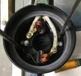
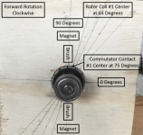
The common issue with trolling motors is that higher pitch boat propellers in that size range are usually right hand and trolling motors use left hand propellers. I am trying to determine the proper location of the brushes/commutator for for reverse rotation, and to make that correction by rotating the magnets on a Newport Vessels NV86. Rotation of the magnets is accomplished via an adapter ring to rotate the bolt pattern (see picture below of rotated mounting holes for the long bolts). By inspection, the brushes and magnets are aligned, and the commutator is advanced by 11 degrees from that same alignment (see picture below). In the OEM configuration, the no load speed (1,930 RPM) and current (1.4 Amps) are the same for both directions (already in neutral plane?). I rotated the magnets 22 degrees clockwise (from perspective of the motor diagram below). The rotated magnet configuration no load RPM and current remained the same for the reverse direction. However, the forward direction RPM increased to about 2,250, and so did the current (I lost my notes for this measurement). That raised questions about my method. Is the rotation of the magnets a viable method, how can I calculate the proper rotation, and how can I verify that it was performed correctly? Is it possible that the motor is in the neutral plane already given the no load measurements vs. the geometry shown in the picture below?
 

Attachments

  • Rotated Magnet.jpeg
    Rotated Magnet.jpeg
    49.7 KB · Views: 446
  • NV86 Diagram post.png
    NV86 Diagram post.png
    85.1 KB · Views: 446
Hi,
For trolling, the standard design of the 2-pole ceramic PM motor aligns the brushes directly with the center line of the magnetic pole. This puts the armature field in quadrature with the stator field. Magnetic neutral = mechanical neutral. No shift (advance) is used. If direction of rotation is reversed, position of brushes and magnets should be left as built at the motor factory. There is no design difference between a factory cw or ccw motor.
Regards,
major
 
Hwy89 - Reversing the polarity is not useful for long term usage if the brushes are not near the neutral plane. Otherwise there is excessive wear on the brushes and commutator when the current is not at a minimum.

Major - Thanks, that seems to be the case based on the no load measurements. It just isn’t clear to me based on the angle of the commutator to the armature field. There are a lot of internet discussions of folks trying to make LH propellers to increase the pitch, maybe that is all unnecessary? It is simple enough to switch the polarity inside the trolling motor.
 
Penobscot17 said:
Hwy89 - Reversing the polarity is not useful for long term usage if the brushes are not near the neutral plane. Otherwise there is excessive wear on the brushes and commutator when the current is not at a minimum.

Major - Thanks, that seems to be the case based on the no load measurements. It just isn’t clear to me based on the angle of the commutator to the armature field. There are a lot of internet discussions of folks trying to make LH propellers to increase the pitch, maybe that is all unnecessary? It is simple enough to switch the polarity inside the trolling motor.

Hi Peno,

The brush shift (many call it 'advance') is advantageous due to armature reaction under load distorting the main field flux distribution asymmetrically. For wound field motors the steel pole faces provide path for armature flux perpendicular or tangentially, whereas with ceramic magnets, the reluctance of this path is quite large so the distorting flux is minimal. Little if any commutation improvement is gained by repositioning brushes off neutral, only field weakening which is undesirable in a trolling motor.

Regards,
major

ps.
Neutral position can be determined by driving motor at same RPM, measuring open circuit voltage in both cw and ccw rotation. Provided well seated and non-rocking brushes, generated voltage will be equal
 
The goal was never to advance for reverse, but rather to duplicate the OEM forward configuration for reverse operation. Based on your test, it looks like it was already neutrally timed. I recorded 11.5 volts CCW and 11.3 volts CW at 868 RPM. The 0.2 volt difference is likely within the assembly tolerance of the magnet assembly. I would adjust and test, but I already have silicone on the fairing assembly. I do not understand how the commutator angle that I measured is neutrally timed, but I do not want to tear it down again to figure it out. Thanks again, it looks like I am good to go with the RH propeller. As the speed increases, you quickly realize how poorly trolling motors are configured for hydrodynamics. I made a few modifications, and the flow is very clean and quiet now.

NV86 Side with Cavitation Plate.jpeg
 
Back
Top