75mA for the opto's LED is too much, the datasheet mentions 60mA as the "Maximum Absolute Value" (parameter If).
The opto's transistor needs to saturate, because in this case you want it to "turn ON" as much as possible (right?). For it to saturate you need to give a base current that will make it have a collector current higher than the current that will flow through it and R100 and R101 (no current will flow to the MOS). In a quick calculation, we know that the SP node of the circuit will have 3V minimum, and with R100 and R101 this translates to 3V / (21K + 22.1K) ~ 68uA; so we need to set the opto's transistor base current to be comfortably higher than 68uA, it can be much higher. Since this is an opto, we don't deal with base currents; the 4N25 datasheet's tells us that this device has a CTR
* >= 20%, which means that the collector current will be 20% or higher of the LED's current (not in all situations but let's simplify here). So for you to get 68uA of collector current you need an LED current of 68 uA / 0.20 = 340uA or higher. Let's set it to 2mA to be on the safe side.
In your circuit you have the 5V rail. When the EBRAKE closes, current will flow from there to GND, going through the opto, R103 and 1N4007 (a 1N4148 will do it and is a tad smaller and cheaper). The opto will take some voltage (the "diode forward voltage drop") out of the 5V, the 1N4007 will take some more and R103 will take the rest. 1N4007 will take out around 0.65V, the opto will take at most 1.5V (value from datasheet, Vf) so we reach 5 - 0.65 - 1.5 = 2.85V that is what R103 will see. Using Ohm's Law (again) and knowing we want 2mA through the opto's transistor (the same current will flow through the opto, R103 and D1 since they are in series) we calculate R103: 2.85V / 2mA = 1425 ~ 1.5K. All of this is an approximation, a starting estimate. As an interesting check, you can see that picking your current R103 value of 39 Ohm, it gives 2.85V / 39 = 73mA pretty close to the 75mA you mention.
The -EBS voltage when the EBREAK is applied is just D1's voltage drop, with the amounts of current we're talking here it shouldn't go over 0.8V.
You can raise R100-101 further to further reduce the impact on SP if needed. The current that the R100-101 branch pulls from SP is coming not from SP (it is an input) but from the 5V rail through the Throttle and R8, with a bit of influence from R9. I see that you mention the variable-resistor throttle but are modeling using the Hall throttle input... shouldn't you be using the throttle connector SLA pin instead of SP?
C1 shouldn't be needed, although it won't hurt.
"Sag" is a generic term, I used it because I though you would understand it better
")
. Let's call it by its EE name, "voltage drop". The drop I'm mentioning is the drop inside the voltage source. In the case of the 5V rail, since it comes from a 7805, it's not important to model it because your circuit is taking very little current and the 7805 has a relatively low internal resistance which won't cause any relevant voltage drop on the 5V rail. 7805 datasheet says ~8mOhm for internal resistance (they call it "output impedance" because it's dynamic and is a resistor in series with the output) so if your circuit draws 20mA (which it doesn't) that represents a drop of 20mA * 8mOhm = 0.16mV on the 5V rail - totally irrelevant.
However, if you modeled your SP point as a voltage source (you would replace R8, R9 the throttle and the 5V rail by a single voltage component that you could configure to give a ramp of voltage simulating a throttle), then the internal resistance wouldn't be irrelevant anymore because it's high compared to the current you draw from it, which you already found out.
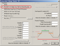
As for the advanced settings of the voltage component. You are now simulating 5s of your circuit (.tran 5). Let's say you want to make a ramp on the 5V rail from 0 to 5V, from second 1 to second 4. You would set
Vinitial = 0 (your starting or "base" voltage)
Von = 5 (your final or "top" voltage)
Tdelay = 1 (1s at Vinitial before starting; this delay applies only to the 1st waveform cycle)
Trise = 3 (you have 3s to go from 0V to 5V, since we want to start at time = 1s and end at time = 4s)
Tfall = (empty, in this test you don't care about the fall time because the test will end before reaching it)
Ton = (empty, as Tfall)
Tperiod = (empty, as Tfall)
Ncycles = (empty, as Tfall)
Sorry for the text length, but it seems to me that you're the kind that likes to learn how to fish and not only be given the fish
Have a nice drink
!
* CTR = Current Transfer Ratio - transfer ration from "input" (LED) to "output" (transistor)