TSDZ2 EBike wireless standard (like Specialized Turbo Levo) - OpenSource

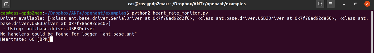
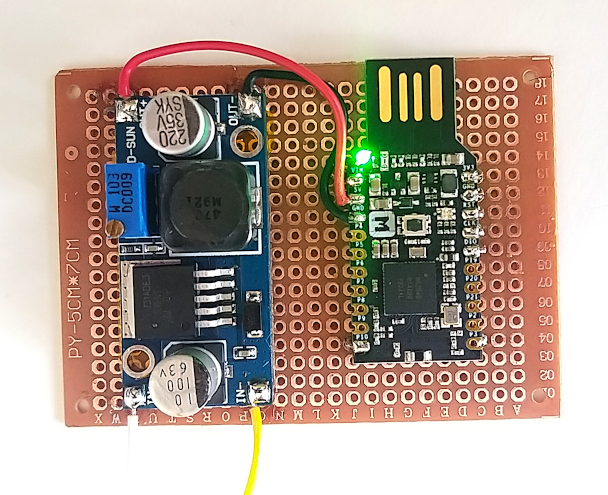
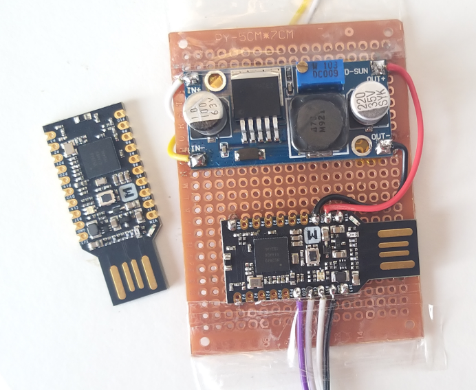
I connected an ANT usb dongle to my PC. I used the Python https://github.com/Tigge/openant and did run the examples/heart_rate_monitor.py , which worked and could read my heart rate value which my watch broadcast:

image.png


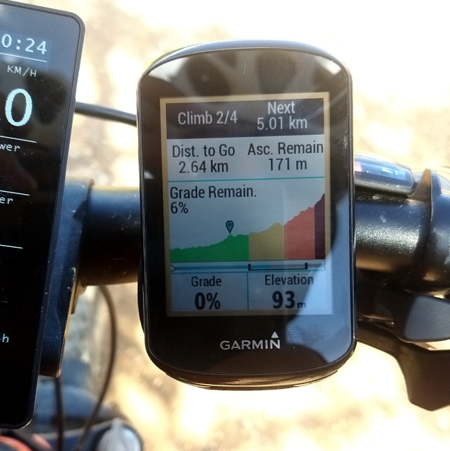
This option is nice because means I can use my PC as an ANT+ LEV ebike, which will be much faster to test and develop than using my Garmin Edge for it. Still, this means I would have to implement the LEV profile on this Python library.
 
I got the board and did solder it with the DC-DC converter board:

image.png


Now I wish to have a solution to turn on/off the power to the TSDZ2 controller - this means that 2 boards always powered but they should use very low energy. Does anyone know a solution to turn on/off the 60V from battery to motor controller voltage input? I guess the current flowing is low, like 250mA.

We did a trip on last 5 days, 3 ebikes with TSDZ2 and 1 ebike with a Bosch motor. I really hope to use this project for our future trips and have less cables / risk of something fail:

image.png


Also I love the feature Garmin Climb pro that shows ahead the next climb - I want to remove the 860C display from my handle bars as soon as possible:

image.png
 
casainho said:
Does anyone know a solution to turn on/off the 60V from battery to motor controller voltage input? I guess the current flowing is low, like 250mA.

I think a DC-DC solid state relay is what you need. For example :

s-l500.jpg


Input : 3 to 32V
Ouput : 5 to 60V

I'm already using it for a DIY CNC wood machine to enable/disable the laminate trimmer (from a 5V output of a Arduino board) and it works perfectly. That's plug & play.
 
casainho said:
Does anyone know a solution to turn on/off the 60V from battery to motor controller voltage input? I guess the current flowing is low, like 250mA.

I think You could use so called "high side switch" on mosfets.
Here is tutorial: [youtube]n3H7y3JhOAk[/youtube]

Here is an example of dc dc converter with dual output 12V and 5V - it can be used to help drive mosfets.
https://www.aliexpress.com/item/32979806475.html?spm=a2g0s.9042311.0.0.27424c4dqZwSSt

And here example schematics and BOM from JLCPCB that i used and tested.
If you change Q1 mosfet to one that you can drive from logic level you are ready to power on TSDZ2 controller.
 

Attachments

  • high-side-switch.jpg
    high-side-switch.jpg
    20.5 KB · Views: 1,791
  • high-side-switch-bom.jpg
    high-side-switch-bom.jpg
    37.9 KB · Views: 1,791
Thanks for the suggestions. After looking at the solid state relay on ebay, I found one that seems better and cheaper: BSP75N.

I want something that is small, light, cheap and uses very low power for not drain the battery. Also one that is simple as possible to solder because I think that this board will be DIY as I do not plan (I don know how to do it) to design a board and sell it.

The BSP75N should use something like < 100 micro amps.
(Seems there are other alternatives like BST117).

I hope they can really work with the 60V:

image.png


image.png
 
Why not just use the Mosfet in your BMS? Most of them have an option for a button to disable the output. On my chinese bluetooth BMS i can disable the output by BLE, too...
 
shaddi said:
Why not just use the Mosfet in your BMS? Most of them have an option for a button to disable the output. On my chinese bluetooth BMS i can disable the output by BLE, too...
Because the idea is to replace the current on/off button of display to a on/off switch controlled by the wireless board, so the system can be turned on/off using a remote wireless button or the mobile phone.

Like this one, fully wireless: https://www.liv-cycling.com/global/campaigns/ridecontrol-handlebar-system/23297

image.png
 
casainho said:
casainho said:
On my side, testing the sample code for receiving HR from an ANT+ HR sensor and send it as a BLE HR sensor:
My board is missing the antenna, there is the connector to it but I lost the antenna.

I tested 3 different example codes of Nordic SDK ANT+ (with 2 different softdevice versions) and none of them worked, still, the code that implemented Bluetooth and ANT+ simultaneous, the Bluetooth works as expected. My plan now is to wait for the NRF52840 boards I bought for this project, that will take probably more 3 weeks to arrive. I will take this time to learn more about the ANT+ LEV profile, as there is no sample code on the Nordic SDK.
I am having the same issue with this new board, Bluetooth works but ANT does not - probably I am doing something wrong... maybe something about the ANT+ key?? I am running the ANT+ Heart Rate sensor (TX) example but the sensor is never available, I checked on my Garmin Edge and on PC with a USB ANT stick.

Could be possible that for ANT the board antenna or something on hardware must be different for ANT? at least there is the code example that should work both simultaneous for Bluetooth and ANT so the hardware can be the same.
 
The BSP75N and the BST117 won't work to switch the 60 volts. They are low side switches (to switch the ground), what you need is a High Side Switch like the BTS4140N for example.


casainho said:
Thanks for the suggestions. After looking at the solid state relay on ebay, I found one that seems better and cheaper: BSP75N.

I want something that is small, light, cheap and uses very low power for not drain the battery. Also one that is simple as possible to solder because I think that this board will be DIY as I do not plan (I don know how to do it) to design a board and sell it.

The BSP75N should use something like < 100 micro amps.
(Seems there are other alternatives like BST117).

I hope they can really work with the 60V:

image.png


image.png
 
casainho said:
shaddi said:
Why not just use the Mosfet in your BMS? Most of them have an option for a button to disable the output. On my chinese bluetooth BMS i can disable the output by BLE, too...
Because the idea is to replace the current on/off button of display to a on/off switch controlled by the wireless board, so the system can be turned on/off using a remote wireless button or the mobile phone.

Like this one, fully wireless: https://www.liv-cycling.com/global/campaigns/ridecontrol-handlebar-system/23297

image.png

Hi Casainho,

Unfortunately I think Giant has the buttons wired.

It appears that the 2020 version of the RideControl one buttons also has ANT +. The 2019 version only had bluetooth.

giant ride control One.jpg
 
casainho said:
Now I wish to have a solution to turn on/off the power to the TSDZ2 controller - this means that 2 boards always powered but they should use very low energy. Does anyone know a solution to turn on/off the 60V from battery to motor controller voltage input? I guess the current flowing is low, like 250mA.

You could try one of these:-

https://www.seeedstudio.com/Grove-Optocoupler-Relay-M281-p-2923.html

Simple design, the spec sheet of the M281 IC are on the above page also the schematic and PCB layout. It has the advantage of being isolated as well as 1A continuous @60V, so you can use it low or high-side - plus it will help reduce RFI :bolt: getting into the dongle.
 
I have good news:

- I got the ANT+ heart rate sensor example code working, that my Edge GPS cycling computer immediately detected. The issue was very simple, I was not setting up the ANT+ keys. The 4 wires seen on the picture are the JTAG SWD for flash and debug the code.
To recap, Bluetooth and ANT+ example code from the manufacturer is working on this board, as expected.

- I received my second NRF52840 board as seen on the picture. I want to cut the USB connector area because it is not needed and will make the board small. That space can be used for the switch to power on/off the TSDZ2 motor controller.

image.png


- I found PlatformIO that supports NRF52840, using Arduino C++ or MBED. There is a new TSDZ2 motor controller version with a very different microcontroller that is supported by PlatformIO but Arduino only, so, maybe could be good to go with PlatformIO and Arduino for both projects -- the only issue is that I am not sure Arduino supports ANT+... and I am not very familiar with C++ and Arduino, I am much more with the Nordic example code...
And PlatformIO uses the Visual Studio Code which seems a much more modern IDE compared to Eclipse for developing for ARM and STM8, as I am doing currently...
 
I was just playing around with some ideas in KiCAD that would be useful to me :oops: , if not anyone else:-
View attachment nRF52_Dongle.pdf
I don't know how many spare GPIO the nRF52 has, or what they are capable of (I think I read somewhere that they are all pin-assignable?) but you could easily lose some of the functions if necessary. For a wireless project it probably has too many wires, but for things that will always stay on the one bike (brake levers(!), lights, horn etc.) it might tidy things up?

I like the idea of unlocking/turning on via the app, but it would be useful to have a back-up way of unlocking it when running headless and having lost your phone! I also like the idea of using the horn and lights as an alarm - but I can't think of a way to trigger it without using an extra sensor. Accelerometer, vibration sensor, Bluetooth out-of-range?

If you can find an ANT+ library for the Arduino platform it would definitely make it easier for end-users to add hardware and code. I'm probably wrong, but I thought Arduino also used to allow the use of C code as well as C++? My memory is a bit hazy so I could be mixing it up with AVR Studio - I've used them both but only intermittently....
 
Headless said:
I was just playing around with some ideas in KiCAD that would be useful to me :oops: , if not anyone else:-
nRF52_Dongle.pdf
I don't know how many spare GPIO the nRF52 has, or what they are capable of (I think I read somewhere that they are all pin-assignable?) but you could easily lose some of the functions if necessary. For a wireless project it probably has too many wires, but for things that will always stay on the one bike (brake levers(!), lights, horn etc.) it might tidy things up?
I think for a start, using the wireless board + power board is a good idea, so, we are limited to the free pins on this board. For now the used pins are:
- JTAG SWD: 3 pins
- UART TX and RX for TSDZ2: 2 pins
- TSDZ2 on/off power switch: 1 pin

Headless said:
I like the idea of unlocking/turning on via the app, but it would be useful to have a back-up way of unlocking it when running headless and having lost your phone!
At least 3 options to turn on/off the system:
- using the wireless remote button (can be an ANT+ and/or Bluetooth button)
- using mobile app
- using smart watch (realistically, can be a Garmin watch with a custom app for full control our ebike)

I plan to install the wireless remote button and I always carry with me my mobile phone and my garmin watch.

Headless said:
I also like the idea of using the horn and lights as an alarm - but I can't think of a way to trigger it without using an extra sensor. Accelerometer, vibration sensor, Bluetooth out-of-range?
Alarm would be another feature and more features means a more complex system. Alarm is important feature and can be complex, with IOT. Maybe better to have a separate system (like the battery BMS) and integrate with the system using the Bluetooth, as the Bluetooth will always be running.

Would you like to start make the schematic using Kicad for the first version? to help make the documentation for when new users need to solder the wires and the various boards?
 
casainho said:
using the wireless remote button (can be an ANT+ and/or Bluetooth button)

I've never used wireless buttons, but I did see a Youtube video where an ANT+ ebike button seemed to have ~1s delay. I know it will be heavily application dependant, but do you think the Walk function and Virtual Throttle will still be usable? That (and batteries!) are my only concerns with wireless. For brakes it would be easy to keep them separate and dual-purpose the same box as a wiring nest.

casainho said:
Alarm would be another feature and more features means a more complex system. Alarm is important feature and can be complex, with IOT. Maybe better to have a separate system (like the battery BMS) and integrate with the system using the Bluetooth, as the Bluetooth will always be running.

This is well out of my comfort zone :cry: I can wire up and program an ATMega328, but IOT and Bluetooth are... younger than I am!

casainho said:
Would you like to start make the schematic using Kicad for the first version? to help make the documentation for when new users need to solder the wires and the various boards?

I have plenty of time on my hands at the moment, so just let me know what you want and I can cobble something together. I'm not a superuser or anything, but I can handle stitching together a bunch of off-the-shelf modules.
 
Headless said:
I've never used wireless buttons, but I did see a Youtube video where an ANT+ ebike button seemed to have ~1s delay. I know it will be heavily application dependant, but do you think the Walk function and Virtual Throttle will still be usable? That (and batteries!) are my only concerns with wireless. For brakes it would be easy to keep them separate and dual-purpose the same box as a wiring nest.
Garmin and other companies sells specific ANT+ ebike remote buttons so I bet they work for this application. One company say the battery work for 100h - 100h of click should be plenty!! (also note that this devices do report their battery state).

Headless said:
I have plenty of time on my hands at the moment, so just let me know what you want and I can cobble something together. I'm not a superuser or anything, but I can handle stitching together a bunch of off-the-shelf modules.
The board is this one: https://wiki.makerdiary.com/nrf52840-mdk-usb-dongle/

The power board is the one bought on ebay, the most cheap fro 60V input.

Draw a simple schematic. Include the BTS4140N to power on/off the TSDZ2 power, see the previous discussion here.

Give me your github ID so I can add you with write access to the repository and then you can push your files of the schematic to: https://github.com/OpenSource-EBike-firmware/TSDZ2_wireless
 
casainho said:
Draw a simple schematic. Include the BTS4140N to power on/off the TSDZ2 power, see the previous discussion here.

Give me your github ID so I can add you with write access to the repository and then you can push your files of the schematic

No Github account yet - will do both tomorrow.
 
@raw, do you have any news on the mobile app?

I am being thinking on the structure on the firmware from my side and sure it will need the configurations done on the mobile app...
 
@casainho - do you want the whole KiCAD project or just the .pdf? I also have the supporting datasheets I can upload.

The BTS4140 control input floats for off and is pulled-down to be active - I have included a mosfet as per the datasheet. This can be omitted is you are happy that no glitches will occur on power-up. I assume you would change between High-Z input and Low output?

I also included notes and wiring for the brakes, but not the throttle. I have tried to get the Tx/Rx the correct way round and guessed the GPIO to use - please let me know what you decide on. BTW, the pin-numbering for the dongle is insane, but I stuck with the documentation! :lol:

Let me know where you want it uploaded.
 
Headless said:
@casainho - do you want the whole KiCAD project or just the .pdf? I also have the supporting datasheets I can upload.
I gave you write access. Put the full source files on the schematic folder as also all other files like the PDF or a JPG. A JPG is better for then show here on the forum.

Headless said:
The BTS4140 control input floats for off and is pulled-down to be active - I have included a mosfet as per the datasheet. This can be omitted is you are happy that no glitches will occur on power-up. I assume you would change between High-Z input and Low output?
The idea is to make a quick and dirty board, less components possible and soldering required, so less barriers for new users. This board will be DIY so the success of the project will depend on the easy to source and build!!

Headless said:
I also included notes and wiring for the brakes, but not the throttle. I have tried to get the Tx/Rx the correct way round and guessed the GPIO to use - please let me know what you decide on. BTW, the pin-numbering for the dongle is insane, but I stuck with the documentation! :lol:
I think brakes can be optional (I use them) and the system will be fully wireless only when not using brakes. (Maybe brakes can be protected against short circuit, high voltage injection and have a magnetic connector??).

Fell free to document on the documentation folder, on the README.md file (look on web for Github Markdown syntax). Upload the JPG files to that folder and you can use them on the README.md file.

Yes, you will need to understand the git commands like git checkout, git log, git commit, git pull and git push.
 
@casainho - Hmmm, I'm not confident that I know what I'm doing! Generally...

casainho said:
The idea is to make a quick and dirty board, less components possible and soldering required, so less barriers for new users. This board will be DIY so the success of the project will depend on the easy to source and build!!

I'll make a note to add a diode to Brake Input and remove the mosfet on the next version. Anything else? It's pretty simple so far!
nRF52840_Wiring.jpg
 
I noticed that the nRF52840 dongle has an RGB LED which could be used to flash error codes? If you go for a truly minimal set-up you could protect it in "transparent" heatshrink so you can still see the LED, and seal the open ends and motor-controller cable with hot-glue or silicon. As long as you're neat, you can slice the heatshrink open fairly easily if you need to do further hardware mods.
 
Headless said:
@casainho - Hmmm, I'm not confident that I know what I'm doing! Generally...

casainho said:
The idea is to make a quick and dirty board, less components possible and soldering required, so less barriers for new users. This board will be DIY so the success of the project will depend on the easy to source and build!!

I'll make a note to add a diode to Brake Input and remove the mosfet on the next version. Anything else? It's pretty simple so far!
That's perfect!!

There is one thing missing that is the labeling for the flashing pins to the STLinkV2 (it will be just like for the SW102 display).

That blocks on the schematic can be divided on different images and put on the README.md file, where more detail notes in text can be added to help users understand all this.

The only piece of hardware I don't have with me is the BTS4140N but I already bought it, may take 2 week to arrive. So, this is almost fully tested.

And yes, that the hardware is very simple!!

Now, I need to focus on the firmware side. And the mobile app is really needed because there are a lot of TSDZ2 configurations that can be possible only over Bluetooth on a mobile app, so we need the development for firmware ANT+ ebike + Bluetooth mobile app.
 
@casainho - Can I just check one thing? What is the voltage of the TSDZ2 motor-controller's UART?

Given the brake input is pulled up to 5V I would have assumed that the procesor was running at 5V, but 3.3V seems to be the correct voltage for flashing it? The nRF52840 does not have 5V-tolerant GPIO when running at 3.3V and I can't find any mention of protection diodes to the power rails, which might be the case if they want to save every picowatt? It would make the GPIO rather vulnerable to :bolt: :flame: though....
 
Back
Top