Using an electric skateboard motor controller without a remote

Tezzy

1 µW
Joined
Jun 11, 2016
Messages
4
Hi everyone,

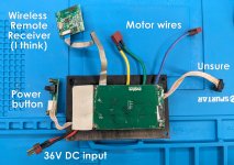
I have an Evolve Skateboards motor controller that I want to re-purpose to control a brushless motor in a cordless snow blower, rather than spend $60CAD on a new e-bike controller. The problem is, the skateboard motor controller is controlled via a wireless remote and I need to control it using the lever built into the Snow blower handle which is a simple on/off switch. Does anyone know how I could use this controller to power a motor without the wireless remote? I don't even need variable speed, just an on off switch. The controller is from an old Bamboo single motor Evolve board.
 
If the controller has a physical throttle input, you can use that, but if it doesn't:

Wire the blower handle to the remote's physical throttle input using a resistive voltage divider to give the voltage that provides the correct motor speed for your blower.

It's likely the remote's throttle is a hall sensor, so you can disconnect it's signal pin from the board and wire one side of the blower's switch there instead. The other side of the switch goes to the voltage divider's center connection.

The voltage divider can simply be a 10kohm potentiometer, outer wires wired to 5v and ground, center tap is then the throttle signal. Adjust the pot while the blower switch is on until the motor spins the right speed.
First of all thanks very much for taking the time to write that. My electronics knowledge is quite basic, so I don't know my way around an ESC like this and there is no label for the throttle signal pin. Looking at these photos can you determine any more than I can? I should mention I no longer have the remote. And the Snow Blower is an ION18SB, which does not have hall sensors.

I should also mention that there is nothing wrong with the snow blower controller, but I do not have an original Snow Joe battery and it will not accept my DIY battery because between the + and - pins there is an ID pin which seems to detect that I'm not using a branded battery and I have not been able to find a way around this, so I'm trying to replace it with my own controller from the skateboard.
 

Attachments

  • ESC 2.jpg
    ESC 2.jpg
    2.3 MB · Views: 9
  • PXL_20231126_195004808.jpg
    PXL_20231126_195004808.jpg
    2.9 MB · Views: 7
Last edited:
First of all thanks very much for taking the time to write that. My electronics knowledge is quite basic, so I don't know my way around an ESC like this and there is no label for the throttle signal pin. Looking at these photos can you determine any more than I can? I should mention I no longer have the remote. And the Snow Blower is an ION18SB, which does not have hall sensors.

Without the remote for it, then unless it has a throttle input somewhere you can't use it without getting a new remote for it.

If the remote receiver board outputs a standard throttle signal, you can connect the resistive divider or pot in place of that.

Since you don't have the remote it's hard to test for this, but probably not impossible. A throttle that is inactive usually outputs about 0.8v. If the board fully emulates a real throttle then if you have a voltmeter you can measure from battery negative to the pins on the cable that goes between the small board and the main control board (J2 on the main board). If you had the remote you could vary it to then find the pin that varies with it on that cable. You'll need the main power connected to the controller to do this test, even if you have no motor attached. Post what you get here, perhaps marked on the picture.

On the J2 connector there are some pins that don't go anywhere at all. Some on the "left" go to a set of parts that look like a small SMPS that probably powers that remote board. Some of the ones to the right of that go off to the MCU, and are probably either serial communication or analog control lines. It's much more likley to be serial comms, and that there's no analog signal to be found or used, but it's worth a test to see if there's anything obvious.

it's also possible that one of the pads on the edge of the remote receiver board is for a throttle test input, but I don't know a good easy way to test for that without actually connecting a potentiometer or a hall throttle signal output to the non-ground / non-power pins one at a time, and vary them, to see if they will make the controller drive a motor.


I should also mention that there is nothing wrong with the snow blower controller, but I do not have an original Snow Joe battery and it will not accept my DIY battery because between the + and - pins there is an ID pin which seems to detect that I'm not using a branded battery and I have not been able to find a way around this,
There's another thread you posted in about a mower with this problem, so if you can do the tests suggested there on either the blower or the mower, we can try to determine if it might be possible to work around that; it's likely that if both systems use the same battery they'd work identically for this part. If not you'd have to do those tests on this blower, too.
 
Without the remote for it, then unless it has a throttle input somewhere you can't use it without getting a new remote for it.

If the remote receiver board outputs a standard throttle signal, you can connect the resistive divider or pot in place of that.

Since you don't have the remote it's hard to test for this, but probably not impossible. A throttle that is inactive usually outputs about 0.8v. If the board fully emulates a real throttle then if you have a voltmeter you can measure from battery negative to the pins on the cable that goes between the small board and the main control board (J2 on the main board). If you had the remote you could vary it to then find the pin that varies with it on that cable. You'll need the main power connected to the controller to do this test, even if you have no motor attached. Post what you get here, perhaps marked on the picture.

On the J2 connector there are some pins that don't go anywhere at all. Some on the "left" go to a set of parts that look like a small SMPS that probably powers that remote board. Some of the ones to the right of that go off to the MCU, and are probably either serial communication or analog control lines. It's much more likley to be serial comms, and that there's no analog signal to be found or used, but it's worth a test to see if there's anything obvious.

it's also possible that one of the pads on the edge of the remote receiver board is for a throttle test input, but I don't know a good easy way to test for that without actually connecting a potentiometer or a hall throttle signal output to the non-ground / non-power pins one at a time, and vary them, to see if they will make the controller drive a motor.


There's another thread you posted in about a mower with this problem, so if you can do the tests suggested there on either the blower or the mower, we can try to determine if it might be possible to work around that; it's likely that if both systems use the same battery they'd work identically for this part. If not you'd have to do those tests on this blower, too.
Thanks a lot for this once again. I poked around with a meter and got some readings on the outer pins as shown in this photo. The inner pins had no significant voltage.

I tried your suggestion with the meter on Hz and when I connected the battery it read 3 something for about 3 seconds before reverting to zero. I could not get a reading on subsequent tries. I'm not sure why it only worked the once.

The other thread I posted in was one about the same snow blower, but it belongs to someone else and I just asked another poster if he ever found a solution. The OP of that thread had an older model without the battery ID check and was able to use his own battery, but the poster I asked had a later production unit like mine with the ID system and they were struggling to get batteries to work. There is no reliable info about that system online that I can find. Someone who modified the same snow blower told me in a Youtube comment that a simple high ohm 2 resistor voltage divider with the join connected to the middle pin of the blower is all that's required for these blowers, but I don't think that's correct and having tried it that just shorted out the battery and heated up the resistors very quickly without solving the problem. I think it's looking for a more complex signal than that; something I can't provide without going deep into Arduinos and custom code. And that's too difficult for me and probably not worth the time trying anyway.

So that leads me to replacing the controller, preferably with the Evolve one as I hope not to spend more money on this blower, but it's it's too difficult I will have to buy one.
 

Attachments

  • 123.jpg
    123.jpg
    1.7 MB · Views: 8
Thanks a lot for this once again. I poked around with a meter and got some readings on the outer pins as shown in this photo. The inner pins had no significant voltage.
It's possible taht the one with 0.4v on it is the throttle signal line. (a throttle that's "off" usually has around 0.8v-1v; so 0.4v isn't outside the possibilities for such a signal that's inactive)

Can you read the part number on the chip to the left of that connector? If it is a chip with an analog output on the pin that connects to the 0.4v pin of the connector, then it probably is a throttle signal, and you can then try inserting your own throttle signal there to see what happens.


I tried your suggestion with the meter on Hz and when I connected the battery it read 3 something for about 3 seconds before reverting to zero. I could not get a reading on subsequent tries. I'm not sure why it only worked the once.

If it was only 3hz, then that's probably spurious signal from an outside source. You'd probably see something like 8-20khz (thousands to tens of thousands of hz) if it was a serial data signal, and it would be consistent.


The other thread I posted in was one about the same snow blower, but it belongs to someone else and I just asked another poster if he ever found a solution. The OP of that thread had an older model without the battery ID check and was able to use his own battery, but the poster I asked had a later production unit like mine with the ID system and they were struggling to get batteries to work. There is no reliable info about that system online that I can find.

That's unfortunatley true of most of these (especially since manufacturers change things without notification to end-users frequently; it's not uncommon for some brands to end up with incompatible parts between things that were the same model number because of this. (in ebike stuff, Bafang does this all the time which screws their dealers and customers over all too often).

Someone who modified the same snow blower told me in a Youtube comment that a simple high ohm 2 resistor voltage divider with the join connected to the middle pin of the blower is all that's required for these blowers, but I don't think that's correct and having tried it that just shorted out the battery and heated up the resistors very quickly without solving the problem.

What proportion of what resistance did they suggest? There will be a specific ratio of resistance between the one that goes from signal to ground (B-) vs signal to B+, and that has to be used to make it work. Also, such a system would have to use resistors with tens to hundreds of kohms (k=thousands) to prevent significant current flow between the B+ and B-, otherwise any battery would self-discharge relatively quickly. If you're not sure then if you can link or quote the YT comment or page I can check.


I think it's looking for a more complex signal than that; something I can't provide without going deep into Arduinos and custom code. And that's too difficult for me and probably not worth the time trying anyway.

It is probably looking for a data signal, but there are some that just use a simple voltage or resistance and are easy to bypass, so it can be worth checking out the simple options first. ;)
 
Back
Top