Relevant background on where I'm coming from: I have only used large cells with post or bolt terminals, connected by wires with crimped ring terminals, each battery terminal only connected to one other terminal, same wire gauge for serial vs parallel.
So I really have a very hard time visualising the current flow through these connection "strips, grids and plates" layouts, where the same terminals are "communicating" with multiple other terminals, both serial and parallel at the same time.
So, to clarify my understanding, what about this "hybrid" 10P14S layout / design as an example:
14 separate sub-pack batteries
each a separate "box" using the welded grid/plate technology usual on this forum internally,
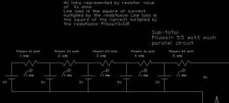
only **one big parallel group** of 10 cells each to get to the 10P
each group terminated from the grid/plate internally, to a [-/+] pair of threaded posts to the outside.
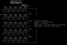
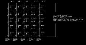
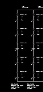
These "group boxes" are then wired in series to 14S
using insulated stranded heavy copper wire, say #2 gauge, to carry 100A bursts, 50A continuous.
Now, my puzzled question:
are the "intra parallel" connections **within** each of those 14 separate sub-pack batteries
truly **such** low current flow?
Take that 50A continuous "through" the 15 serial wires. Given the 10P group of say 2000mAh cells, each cell is getting an evenly divided 2.5C rate (5 amps) current flow through each cell-terminal-to-strip junction?
And so, that is what makes using only 0.15 nickel strips OK? really OK?
So I really have a very hard time visualising the current flow through these connection "strips, grids and plates" layouts, where the same terminals are "communicating" with multiple other terminals, both serial and parallel at the same time.
So, to clarify my understanding, what about this "hybrid" 10P14S layout / design as an example:
14 separate sub-pack batteries
each a separate "box" using the welded grid/plate technology usual on this forum internally,
only **one big parallel group** of 10 cells each to get to the 10P
each group terminated from the grid/plate internally, to a [-/+] pair of threaded posts to the outside.
These "group boxes" are then wired in series to 14S
using insulated stranded heavy copper wire, say #2 gauge, to carry 100A bursts, 50A continuous.
Now, my puzzled question:
are the "intra parallel" connections **within** each of those 14 separate sub-pack batteries
truly **such** low current flow?
Take that 50A continuous "through" the 15 serial wires. Given the 10P group of say 2000mAh cells, each cell is getting an evenly divided 2.5C rate (5 amps) current flow through each cell-terminal-to-strip junction?
And so, that is what makes using only 0.15 nickel strips OK? really OK?