serious_sam
10 kW
Thought I’d share my design for the pre-charge/kill switch circuit that I’ve been using for the last several months. Figured someone else might have some use for it.
During the build of my bike, I was looking to develop a solution for a kill switch that would also function as capacitor pre-charge. There are a lot of posts here on ES about this type of circuit, and I read every one I could find (for example: https://endless-sphere.com/forums/viewtopic.php?f=3&t=40142 ). At which point, I was inspired to develop my own design.
Nothing revolutionary. Just a different flavour to the general theme. The main difference being, that the trigger for switching on the main power mosfets is charge level based (not time based).

Notes:
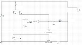
- C3 represents the motor controller (capacitance). 2mF shown here, but it will work with any value.
- Components are sized for 20S pack.
- For 14S or similar, R1 and R2 should be changed to 12kOhm, and R4 should be changed to around 68kOhm.
The circuit works as follows:
1) Closing SW1 sends current through R1 to the gate of the pre-charge mosfet (PSMN7R0-100XS), which turns on, and allows current to flow through R6 (100R 10W), charging the controller capacitors. The zener D4 limits gate voltage to 12V. R5 is required to allow the gate to discharge when the switch is turned off. This pre-charge stage takes about 0.5 seconds with the Nucular 12F which has about 2mF capacitance.
2) Closing SW1 also allows current to flow to the gates of the main mosfets (4x IPB017N10N5LF) through R2, however, the transistor (MPSA42) is switched on by the base current flowing through R4 and zener D3. This transistor is shorting the mosfet gates to ground, holding them off, for now. C2 and R3 are just there to hold the gates low initially for an instant, which gives the transistor time to turn on (ensures that the mosfets are initially off). Shout out to John from work who helped to develop the voltage sensing idea.
3) When the controller capacitor voltage reaches Vbatt-5V (i.e. 90-95% charge), the base current flowing into the transistor stops conducting, allowing the main mosfet gates to pull high (limited to 12V by zener D2) and the main mosfets to turn on. That -5V comes from the transistor base-emitter diode (0.7V) plus the zener D3 (4.3V).
4) Opening SW1 grounds the mosfet gates through R2, R1, and R5, and turns everything off again.
I like this circuit because the delay is not a fixed time period, it is determined by feedback from the charge level in the capacitors (bigger capacitors get longer to charge). And the mosfets are not used/abused in the linear region. Pre-charge is through a dedicated mosfet and resistor. Maybe not as “sexy” as using mosfets as a variable resistor, but all the low Rds mosfets I looked at have poor DC safe operating area performance in the upper limits of their voltage range where they would be operating. Running any significant current through them out of the safe operating area will cause failure (eventually).
The trade-off for using a sense line off the negative side of the capacitor is that a very small current can pass to ground (through R4, D3, and the transistor), even when the circuit is switched off. However due to R4, the allowable current flow is limited to less than 1mA, which IMO isn’t an issue (it would take >2 years to flatten my 15Ah battery).
The main mosfets I used are 4x IPB017N10N5LF (Rds = 1.5mOhm). So at 150A peak current, they’re dissipating about 8.5W total. At 50A that drops to 0.35W. Negligible.
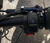
This is the handle-bar switch. Cheapo eBay bike light switch. The mechanism is adequate.

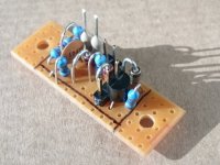
This is the control circuit:

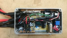
This is the finished unit. Main mosfets are on the copper bar, at the top left of image (hidden under the big soldery globule of 8AWG wire). Power resistor at top right, sitting on top of its mosfet (TO220F insulated case). Control circuit at the bottom of image. The other parts are unrelated: The big PCB in the middle is SMPS for my front light (84V->8.4V). The little one on the right is SMPS for my tail light (8.4V-> 5V). The cylindrical button is the light switch.

During the build of my bike, I was looking to develop a solution for a kill switch that would also function as capacitor pre-charge. There are a lot of posts here on ES about this type of circuit, and I read every one I could find (for example: https://endless-sphere.com/forums/viewtopic.php?f=3&t=40142 ). At which point, I was inspired to develop my own design.
Nothing revolutionary. Just a different flavour to the general theme. The main difference being, that the trigger for switching on the main power mosfets is charge level based (not time based).

Notes:
- C3 represents the motor controller (capacitance). 2mF shown here, but it will work with any value.
- Components are sized for 20S pack.
- For 14S or similar, R1 and R2 should be changed to 12kOhm, and R4 should be changed to around 68kOhm.
The circuit works as follows:
1) Closing SW1 sends current through R1 to the gate of the pre-charge mosfet (PSMN7R0-100XS), which turns on, and allows current to flow through R6 (100R 10W), charging the controller capacitors. The zener D4 limits gate voltage to 12V. R5 is required to allow the gate to discharge when the switch is turned off. This pre-charge stage takes about 0.5 seconds with the Nucular 12F which has about 2mF capacitance.
2) Closing SW1 also allows current to flow to the gates of the main mosfets (4x IPB017N10N5LF) through R2, however, the transistor (MPSA42) is switched on by the base current flowing through R4 and zener D3. This transistor is shorting the mosfet gates to ground, holding them off, for now. C2 and R3 are just there to hold the gates low initially for an instant, which gives the transistor time to turn on (ensures that the mosfets are initially off). Shout out to John from work who helped to develop the voltage sensing idea.
3) When the controller capacitor voltage reaches Vbatt-5V (i.e. 90-95% charge), the base current flowing into the transistor stops conducting, allowing the main mosfet gates to pull high (limited to 12V by zener D2) and the main mosfets to turn on. That -5V comes from the transistor base-emitter diode (0.7V) plus the zener D3 (4.3V).
4) Opening SW1 grounds the mosfet gates through R2, R1, and R5, and turns everything off again.
I like this circuit because the delay is not a fixed time period, it is determined by feedback from the charge level in the capacitors (bigger capacitors get longer to charge). And the mosfets are not used/abused in the linear region. Pre-charge is through a dedicated mosfet and resistor. Maybe not as “sexy” as using mosfets as a variable resistor, but all the low Rds mosfets I looked at have poor DC safe operating area performance in the upper limits of their voltage range where they would be operating. Running any significant current through them out of the safe operating area will cause failure (eventually).
The trade-off for using a sense line off the negative side of the capacitor is that a very small current can pass to ground (through R4, D3, and the transistor), even when the circuit is switched off. However due to R4, the allowable current flow is limited to less than 1mA, which IMO isn’t an issue (it would take >2 years to flatten my 15Ah battery).
The main mosfets I used are 4x IPB017N10N5LF (Rds = 1.5mOhm). So at 150A peak current, they’re dissipating about 8.5W total. At 50A that drops to 0.35W. Negligible.
This is the handle-bar switch. Cheapo eBay bike light switch. The mechanism is adequate.

This is the control circuit:

This is the finished unit. Main mosfets are on the copper bar, at the top left of image (hidden under the big soldery globule of 8AWG wire). Power resistor at top right, sitting on top of its mosfet (TO220F insulated case). Control circuit at the bottom of image. The other parts are unrelated: The big PCB in the middle is SMPS for my front light (84V->8.4V). The little one on the right is SMPS for my tail light (8.4V-> 5V). The cylindrical button is the light switch.


