Help wiring a switch for a lipo booster

GCinDC

100 MW
Joined
Jan 23, 2009
Messages
4,261
Location
Washington, DC
I've got a Ping 48V 12Ah and an 18.5V 10Ah lipo pack. Both have PowerPole leads. For 66.5V, I put the Ping black lead into the controller, and the Ping red into the lipo black, and the lipo Red into the Controller. Has been working well, but sometimes the lipo runs out before I'm done. I can unplug it so both ping wires are connected to the controller, but I want to wire a switch in place. I bought a DPDT switch at radio shack (10A at 120VAC) with positions ON - OFF - ON and each has two connectors. I realize I probably don't need the off, but perhaps I can use it somehow...

I'm not great with switches. Can anyone help by pointing me toward a wiring diagram that might work? I want one ON position to supply 48V to controller. I'd like the other ON position to include the lipo in series to supply 66.5V. Any suggestions??

I remove the battery all the time, so will continue to use the powerpoles from the controller, but am happy to splice them off my existing wires as nec. The switch will be fixed on the battery.

Oh, and for the wiring in series, does it matter which battery's red lead goes to controller, ie which battery the current should flow through?

Thanks for any suggestions!
 
I have the strong feeling smoke possibly flame? will come from that switch when you twist the throttle. Is it rated for the amps you intend to draw through it'?
 
You only need a DPST but since you have a DPDT, double it ( Amps will be 1/2 on each contacts )

Put the Ping + on controller +
Put the Ping - on the commons ( srews in the middle of the switch )
Put the Lipo + on one side of the switch ( use both screws )
Put the controller - on the other side of the switch ( use both screws )
Put the Lipo - on the controller -
 
how's this?
View attachment booster_switch2.jpg

does it matter if i screw/solder the Lipo - to the switch (on screws next to 48V in pic) or should i splice it with the other controller - wire?

ps. the switch is rated 10A at 120VAC, so would that also be 20A at 60V? And with the contacts doubled, it could be rated at 40A?

My controller is 30A but my max continuous is 24Amps...
 
I don't think your switch is up to what you are asking of it. It would last a while at 48v but pushing 70v through it will fry it pretty quick.

Try two of these relays wired in parallel, then with a switch on the handle bars you can switch on the fly. Don't try using the little black ones that are in the pic. They are 30a/12vdc and I cooked a pair like it on 66v/38a. These are better. 25a/ 28vdc x 4 contacts.


https://www.surpluscenter.com/item.asp?UID=2009052412325037&item=11-2420&catname=


007.jpg
 
Agreed. The switch will almost certainly fry. The amp rating for DC is always less than AC because DC will arc across much larger air gaps than AC at at any given voltage.
 
relays -- egad, they're what always fried on my VW Rabbit diesel... :roll:

i know little about switches, and now relays wired in parallel! lol. you guys rock. but that's why i'm here - to learn. :wink:

from the diag on each relay, they look like switches, but it's back to the drawing board... i have no idea how they work and will study the clues.

ps. i'm not sure i want to wire a switch to the handle bars, because i take the battery off at work to charge it, although i do have a chargery checker which i could wire together with switch and velcro to the CA or somwhere. it would be nice to keep closer tabs on that. right now, the checker stays zipped up. either way, it'd be easy enough to reach down to hit the switch -- it's where the gear levers used to be on old bikes!
View attachment 13_atdeskunzipped.JPG
 
Ok, I read up on relays. Makes perfect sense.

I should have mentioned it before, but I have a master switch on the controller. It's puny, on a very thin red wire that's joined with the big + lead inside the powerpole. That would 'always' be switched off before switching between 48V - 66.5V, so there wouldn't be any arcing.

Would that change things, or do you think the switch would still fry?

I love the idea of the relay on the handlebar, but that'll take a while... to get parts and learn... where do you put the relays, anyway? Do you need special housings? Or do you solder onto the spades?

Nicobie, what's all wired up at the top of your pic? Batteries or relays? I thought they were batteries... Is that what you suggest I build?
 
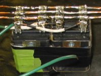
The pic is of 2 of the suggested relays wired in parallel. I used right angle female spade connectors and 12g wire to hook them together. Piece of cake.

As to your switch, It's not the arcing you need to worry about but the current. That switch won't handle that much current.

The 2 relay pack measures 2.5" x 2" x 1.25" and would go with the boost battery. The boost battery would power the coil after running through the little voltage regulator also pictured. The two relays combined draw less than .3a. A small switch could then be mounted anywhere you wish, however it might be a good idea to place it where you would have to take your hand off the throttle when switching. Bad things will happen if you switch under power. :shock:
 
nicobie said:
A small switch could then be mounted anywhere you wish...

Where does your switch go? I see what you've done don't know what's what... Does that relay have the same numbers as other type relays (ie, 85, 87, 30..)?

Any idea where I could find a diagram showing two batts, two switch positions, the leads?

Lucky_Hoodlum said:
I have the strong feeling smoke possibly flame? will come from that switch when you twist the throttle...

I laugh whenever I see this line! :lol:
 
nicobie said:
Try two of these relays wired in parallel, then with a switch on the handle bars you can switch on the fly. Don't try using the little black ones that are in the pic. They are 30a/12vdc and I cooked a pair like it on 66v/38a. These are better. 25a/ 28vdc x 4 contacts. https://www.surpluscenter.com/item.asp?UID=2009052412325037&item=11-2420&catname=

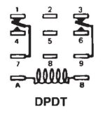
Does this schematic look familiar? (from http://www.deltrol-controls.com/files/rel270.pdf):
Is your relay pack lined up the same way, in terms of the connections, or the other way around?
dpdt.jpgnicobies_dpdt.jpg

Do you suggest I power the relays from my 18.5V lipo, with a resistor to get it down to 12V? Or are they powered by 28V?

PS. I've hunted all over the board for a day and found tons of stuff, from contactors to the schematics thread, but haven't found the answer...

Should I PM Fechter? :wink:
 
Of course, I would never forget the diodes! :lol:
[races to wikipedia to look up diodes...]

So your relay pack is entirely from radio shack?? And it works? I saw some cheap relays there yesterday...

Since this is becoming entertaining.... I'll post a youtube after wiring up the radio shack switch and cranking the throttle! :twisted:

Any bets? Just smoke or FLAME too!?
 
It will work for a little while. You'll never know when it will fail. At least they usually fail in the closed position. My relay pack works fine. I got them from Surplus Center. Just click on the link I posted in the picture post.

It might be useful to read Fechter's thread on the subject;

http://endless-sphere.com/forums/viewtopic.php?f=16&t=1312

Nick
 
Back
Top