Controller started to cut off power under load - Solved

Bigbikebob

10 W
Joined
Jan 27, 2014
Messages
86
Location
Israel
I have a MagicPie 3 motor upgraded 10awg phase wires overclocked to 2KW
connected to External LYEN Edition Controller 12 FET 3077 Mark II Extreme Modder HSL Sensorless controller (with 12awg power wires) and powered by a 48V 20Ah LiFePO4 battery (60A BMS) that can supply up to 40A of contentious current
http://www.conhismotor.com/ProductShow.asp?id=47

I run my controller at 40A which is the upper limit of my battery.
I used my bike in the configuration for about 3 months without any problem.

Yesterday while standing at the foot of a hill ( I climb everyday) I twisted my throttle slowly and got a power cutoff. when I let go of my throttle and tried again, this time more slowly I was able to gain speed and once I was going fast no cutoff happened,
I tried to duplicate the cutoff and was able to do so (many times) while I was trying to start going up the hill.

I checked my setup (the voltage output of the battery was a solid 52.2V while the battery was disconnected from the controller) and could see that my phase bullet connectors looked new, My Anderson connector at the end of the controller power wires looked good. My Anderson connector form at end of my battery had yellow-black color on it.

I reprogrammed my controller to run at 35A and recharged my battery and while riding today had no cutoff.

This problem started after about 3 months and didn't occurred from the start , the question is why and why only under load trying to go uphill?

Edit: I have attached a picture of the controller settings.
 

Attachments

  • Untitled.gif
    Untitled.gif
    155.4 KB · Views: 1,129
First guess is your battery is unbalanced, and a cell or cells is dropping below the BMS's LVC, so it cuts off power to the bike until the cell(s) recover a little.

Or, the cell(s) are simply failing, and need to be replaced.

First thing I'd try is just leaving teh battery on the charger for several days.
 
amberwolf said:
First guess is your battery is unbalanced, and a cell or cells is dropping below the BMS's LVC, so it cuts off power to the bike until the cell(s) recover a little.
Could you explain why the voltage drops and why does it happens under load?

amberwolf said:
First thing I'd try is just leaving teh battery on the charger for several days.
What would this accomplish, and does it recommended to do so from time to time?

Edit: My BMS LVC is set at 35V, My controller LVC to about 29V, So the cutoff is probably from the BMS.
 
Typically lifepo4 like you have performs a lot better with 1.5c discharge rates. Though surely you don't pull 40 all the time, your battery is not liking the 40 amp spikes, like an uphill start. 30 amps would be a better setting for your battery.

So now your weakest cell is showing the strain, likely mostly just not getting fully charged. Leaving the battery on the charger for a long time will help it get all the way full. The green light means the first part of the charge is done, but ideally you leave it on the charger longer so the bms can balance the pack completely. This can take days if really bad.

Hopefully, with a lower amps setting stressing your battery less, it won't get so out of balance in the coming years. Meanwhile, leave your battery on the charger overnight regularly.
 
Bigbikebob said:
amberwolf said:
First guess is your battery is unbalanced, and a cell or cells is dropping below the BMS's LVC, so it cuts off power to the bike until the cell(s) recover a little.
Could you explain why the voltage drops and why does it happens under load?
Mmm...that *is* the explanation. :?

What would this accomplish, and does it recommended to do so from time to time?
It would rebalance the battery, if it is just not getting balanced under normal charging conditions. If it is failing it probably will help a little but not fix the problem.

You should read around the various similar threads others have posted; there's a lot fo them and they go thru all this stuff too.

There are also the many battery repair threads.
 
Thank you both. I left my bike in the charger for the weekend and hope it will solve the problem. From now on will charge overnight.
 
Bob, when you're trying to go up a hill the electric motor is "demanding" more current. This short burst of current required is what's causing the voltage to drop below 35.2 V, which is the LCV (low cutoff voltage) for your motor.

Example, a 10% decrease is voltage results in a 10% INCREASE in current.

The reason why cutoff is in place is because the motor will heat up and become damaged if the current gets too high.
 
I'm afraid you've got a few things mixed up there. :( I'd recommend going thru some of teh basic stuff in the ES Wiki and in some of the various threads listed in the new stickies in the various forums, to refresh your motor control and battery systems knowledge. ;)


--LVC is not for the motor, it is for protecting the cells in teh battery.

--The motor *controller* may also have an LVC that serves two purposes:
---in old SLA systems with no BMS, it was there to protect the SLA from damage by overdischarge.
---in controllers not designed to protect themselves from it, they may also have an LVC to protect them from teh battery going so low that it can't drive the gates/FETs hard enough to fully turn them on, to prevent heat/etc. damage to them.


--The motor controller has a *current* limit to protect the motor, as it doesn't hurt anything to use as low a voltage as you like on the motor.

--The decrease in voltage doesn't result in the increase in current.

--The increase in current results from the motor slowing down under the physical load, which decreases BEMF, and teh controller does what it needs to (increase the average voltage to the motor) to increase the current to get it to continue at teh speed it was at before the load was placed on it.

--The decrease in voltage results from the battery being unable to sustain the current required to do whatever work is being asked of the system.

But the part I bolded below is basically correct.

The part I underlined below would be correct if you were referring to a *current* limit, not an LVC.

jaunty said:
Bob, when you're trying to go up a hill the electric motor is "demanding" more current. This short burst of current required is what's causing the voltage to drop below 35.2 V, which is the LCV (low cutoff voltage) for your motor.

Example, a 10% decrease is voltage results in a 10% INCREASE in current.

The reason why cutoff is in place is because the motor will heat up and become damaged if the current gets too high.
 
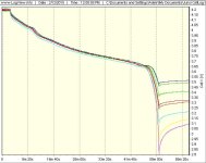
Sometimes people learn more readily with visual aid so here’s a pretty picture graph I captured of an 8S pack battery pack discharging.

1-8Discharge.jpg

Simple description is there’s a load on the pack much like a controller driving a motor. The 8 colored lines represent the voltage measured on each cell in the series string of the battery pack over a period of time.

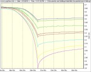
Towards the end (cliff) of the discharge test you can see the lowest capacity cell reach 2.8V which happens to be the LVC (low voltage cutoff) threshold and the BMS switches off to protect the cells from over discharge.

1-8DischargeZend.jpg

Once the load is removed the “resting” voltages drift upwards a bit but for all intents and purposes, that battery pack is empty and should not be used again until it’s been recharged.

When your system cuts out under load, this is exactly what’s happening over and over again and again. It’s really best to not keep pushing things.

Once you hit a LVC the best strategy is to avoid further significant power demand from the system.
 
i think it is because your battery produces contentious current. when they are unruly and contentious then it is almost impossible to make it perform as expected. this is just a reflection of the spoiled attitude most have now so they are all contentious from birth.

if you have anderson connectors that change color from the red or black over to the yellow brown form then it means the current is being misused by the contentious agent and that current wasted in converting it from one color, red or black, over to the yellow brown is not being used to drive the motor. instead that power is being used by the contentious agent to heat up that connector in spite of your efforts to keep it corralled.

you need to stop the contentious agent from usurping your battery power for it's own ends.
 
Hmmmmmm............that sounds like me talking to my grandkids. Interesting explanation of a high resistance connector from a world class scientist. :shock: I like it!
otherDoc
 
First:
Thank you all very much for taking the time to explain subject.
Loved the colorful pictures :)

What I like to clarify is the LVC of the BMS.
At battery Manufacturer web site Discharge Cutoff Voltage is 35.2V. My total voltage is 53.2V after charged. Every cell is rated at 3.2V even if it drops to 0V the total voltage will be 50V.
So the BMS has an individual cutoff voltage for each cell?

Second:
I have tried charging my bicycle for about 3 days and everything was good, but after charging it again for about 36 hours as soon as I started my ride (on a plateau) I got a cutoff.

So it seams I need to locate the bad cell and fix it.
The question is do I only I need to find with low voltage and replace or is there a lot more to it.
 
Before you go there, it’s worth taking a closer look and see if all the cells are actually in balance. That involves measuring each cell on a fully charged pack usually through the balance channels that often connect to the BMS.

Physically replacing a cell is usually not too difficult for someone with good rework skill and fat soldering tip.

Bigger question is it worth the trouble? Newer pack and you can source similar replacements, might be? Older pack and/or hard to find cell replacements, maybe not?

Voltage sag often comes with age so if it’s been several years you may simply have to use that pack mildly until it’s time to go to pasture.
 
I did measure the voltage out of the battery cells connector that goes into the BMS. but not after the battery was fully charged. I got 3.333V on most of the cells and the lowest reading was 3.320V.

In any case from what I have read, you must measure the voltage under stress, and I have no idea how I can connect the battery to the controller and to the voltmeter at the same time.
Is there a special instrument for that?

I have no idea how to make sure the BMS is working as it should.

The pack was used about 6 months so I am not sure it is a good Idea to let it go.

I tried to look around the forum and the internet for some "guide" but didn't find anything that covers the entire process.
 
put your battery on the charger and measure the cell voltages while it is charging. do not take the battery off the charger and measure later. measure while charging. use the 20V scale and list the voltages from cell#1 to the top of Cell #16.

measure on the BMS pcb where the sense wire plug is soldered to the pcb. measure between adjacent pins.

list all the voltages here. .01V resolution.
 
put your battery on the charger and measure the cell voltages while it is charging.
What will it accomplish?

measure on the BMS pcb where the sense wire plug is soldered to the pcb. measure between adjacent pins.
is there no other way? What I mean is what do the guys who build and sell the battery (PING for example) use to balance ,measure and troubleshooting.

Ykick said:
Sometimes people learn more readily with visual aid so here’s a pretty picture graph I captured of an 8S pack battery pack discharging.

View attachment 1
How did you captured the the graph?
 
I have learned (yet again) that you should always start your troubleshooting from the most simple factor and not poke a complex components like the battery :)

I have reprogrammed my controller to a lower ampere to lower the stress on the battery and after I turned the throttle I felt a cutoff but this time I was turning the throttle very slowly and was able to hear the sound of a spark and see it near the motor for a brief moment.

I examined the place more closely and was able to spot a fried isolation on one of the phases.
1.jpg
After I isolated the phase the cutoff was gone.

What is interesting is why the fried isolation was on the phase wire. it is a 10awg wire while the battery and the controller wires are 12awg
 
Phase currents can be much higher than battery.

Could've been physically damaged rather than melted, originally, and then the sparking (lots of heat!) melted it.
 
Phase currents can be much higher than battery.
In the software that came with my lyen controller I do need to program my battery current and my phase current which from what I read is about X2.3-X2.5 more.
 
Remember that yoru controller doens't even have a clue what the actual phase current is, it's only guessing.

When you tell it "2.5x battery current" for phase, your'e telling it to use a guess that phase current is going to be about that much more, and that it should limit at that.

What it actually will be depends on a lot of things the controller doesn't have the stuff to figure out, and isn't programmed to try.

There *are* controllers that do, but typical ebike cotnrollers like that one don't/can't.

But my original point was only to make sure anyone reading would know a possible reason for what happened. :)
 
What it actually will be depends on a lot of things the controller doesn't have the stuff to figure out,

Why is the phase current such a "mysterious creature" and why is it different (and higher) from the actual battery current?

Bigbikebob said:
But my original point was only to make sure anyone reading would know a possible reason for what happened.
And that is a great point :)

All this "damage by current" brings me to ask why e-bikes don't usually use a higher voltage.
It's like the USA home AC 110V that requires thicker wire to transfer more current then the EU 220V in order to supply the same power.
 
Once again confirmed, If it's not the battery it's the wiring, 90% of the time.

Lucky you, phase shorts usually blow the controller. Caught it in the nick of time.

Your original post sure did point towards a battery problem, the way you spoke of it. Funny how many of us you had on snipe hunt. The upside, if your battery is the problem next time, you just learned how to find it. 8)
 
dogman dan said:
Once again confirmed, If it's not the battery it's the wiring, 90% of the time.
Occam's razor FTW :)

It reminds me my dishwasher troubleshooting.
First time it it didn't work I was sure it's the pump and the it was the water pressure.
Second time it didn't work I spent 2 hours testing what I can only to find out that the program dial was between 2 programs.
 
Bigbikebob said:
Why is the phase current such a "mysterious creature" and why is it different (and higher) from the actual battery current?
It's only "mysterious" because cheap controllers like these don't bother to spend the extra on measuring devices and software, as they are mostly not necessary for lower power motors, etc.

Better controllers (including DIY ones like Lebowski's here on ES, commercial ones like the FOC controller from Grin, Adappto's I think, Kelly, and plenty more) do have those things.

As for why it's higher...it's because of several things, but the way you can see it mathematically is that the voltage output to the motor on average is lower than the input voltage from teh battery because of the PWM used to control the motor, and thus for the same wattage (volts x amps) from the battery, the current is higher.

As the motor is driven by the PWM pulses, hte current is very high because when it starts out the wire is just a short circuit, until current thru the inductance of the phase windings builds a voltage up to counter the one from the cotnroller.


Bigbikebob said:
All this "damage by current" brings me to ask why e-bikes don't usually use a higher voltage.
It's like the USA home AC 110V that requires thicker wire to transfer more current then the EU 220V in order to supply the same power.
The first reason is probably because higher voltage like that can be dangerous (lethal!) to the end-user.

In the case of the damaged insulation on yours, if it was damaged first and *then* melted from arcing (the more likely sequence of events), the arcing would have been even greater at the higher voltage, and the heat would have been even greater, too. And the risk of you being injured from electrical shock might have been higher, too, depending on what it was shorted to and if you made contact with that and something else that created a current path.


The second is because various electronic components would also need to be able to withstand that higher voltage, and some of those are (or at least used to be) commonly either less efficient (more heat) or more expensive, or both, for versions that work at higher voltages.

There's other things, too.


But higher voltage doesn't change the phase currents still being higher than battery currents and such, and depending on varoius factors may not decrease the heat involved in some parts of the system.
 
Back
Top